Register file: 0x2F – Digital Diagnostics Interface, sub-register 0x1C is a reserved register. Please take care
not to write to this register as doing so may cause the DW1000 to malfunction.
7.2.48.15 Sub-Register 0x2F:24 – Digital Diagnostics Test Mode Control
Test Mode Control Register
Register file: 0x2F – Digital Diagnostics Interface, sub-register 0x24 is the Test Mode control register.
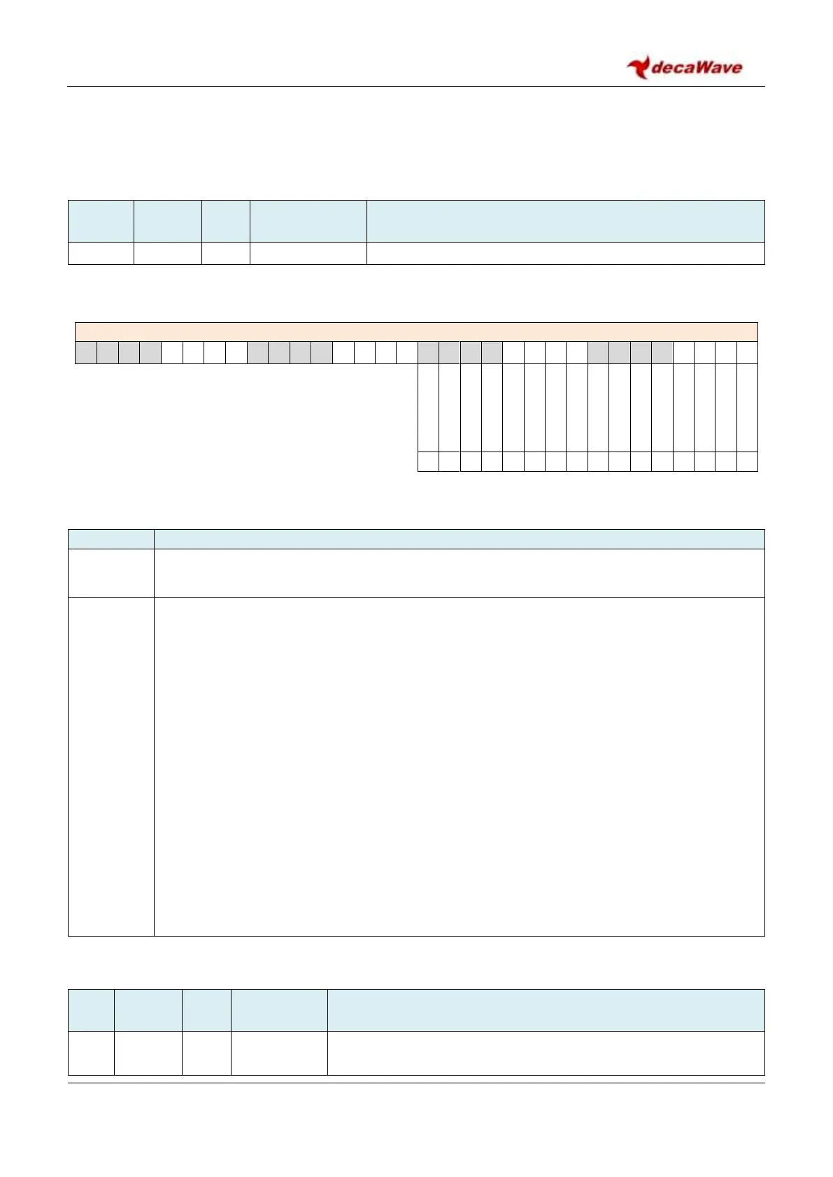
REG:2F:24 – DIAG_TMC – Digital Diagnostics Test Mode Control
The bits of the DIAG_TMC register identified above are individually described below:
Description of fields within Sub-Register 0x2F:24 – Digital Diagnostics Test Mode Control
These bits of the DIAG_TMC register are reserved and should always be set to zero to avoid
any malfunction of the device.
Transmit Power Spectrum Test Mode. This test mode is provided to help support regulatory
approvals spectral testing. When the TX_PSTM bit is set it enables a repeating transmission of
the data from the TX_BUFFER. To use this test mode, the operating channel, preamble code,
data length, offset, etc. should all be set-up as if for a normal transmission.
The start-to-start delay between frames is programmed in the DX_TIME register. This is a
special use of that register, where bits 31 to 0 are used, and the value is programmed in units
of one quarter of the 499.2 MHz fundamental frequency, (~ 8 ns). To send one frame per
millisecond, a value of 124800 or 0x0001E780 should be programmed into the DX_TIME
register. A value <4 should not be used. A time value less than the frame duration will cause
an unpredictable inter-frame spacing and should not be used. To send back-to-back frames
the time value should be set to the frame duration.
When the mode and delay and TX buffer have been configured and the TX_PSTM bit is set, the
repeated TX mode is initiated by setting TXSTRT bit in Register file: 0x0D – System Control
Register.
To exit the Transmit Power Spectrum test mode reset the TX_PSTM bit to zero.
7.2.49 Register files: 0x30 to 0x35 – Reserved
Reserved – these register files are reserved