2.10.3 DSENET® (EXPANSION MODULES)
NOTE: As a termination resistor is internally fitted to the controller, the controller must
be the ‘first’ unit on the DSENet link. A termination resistor MUST be fitted to the ‘last’ unit on
the DSENet® link. For connection details, refer to section entitled Typical Wiring Diagram
elsewhere in this document.
NOTE: DSE6110 MKII & DSE6120 MKII modules does not support the DSE2510 or
DSE2520 display modules.
DSENet® is the interconnection cable between the host controller and the expansion module(s) and
must not be connect to any device other than DSE equipment designed for connection to the
DSENet®
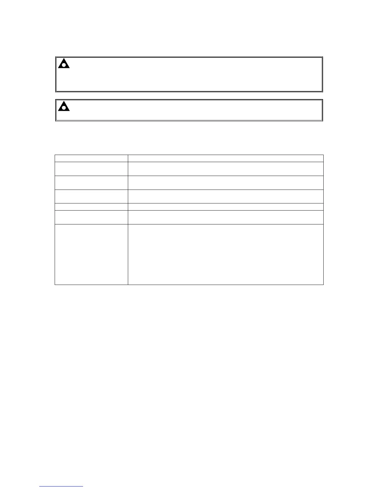
Cable Type Two core screened and shielded twisted pair
Cable Characteristics
120 Ω
Low capacitance
Recommended Cable
Belden 9841
Belden 9271
Maximum Cable Length
1200 m (¾ mile) when using Belden 9841 or direct equivalent.
600 m (656 yards) when using Belden 9271 or direct equivalent.
DSENet® Topology “Daisy Chain” Bus with no stubs (spurs)
DSENet® Termination
120 Ω. Fitted internally to host controller. Must be fitted externally to the
‘last’ expansion module.
Maximum Expansion
Modules
Total 6 devices made up of DSE2130 (up to 2), DSE2157 (up to 2),
DSE2548 (up to 2)
This gives the possibility of :
Maximum 16 additional relay outputs (DSE2157)
Maximum 16 additional LED indicators (DSE2548)
Maximum 16 additional inputs (Can be configured as 4 digital inputs & 4
analogue resistive type inputs or 8 digital inputs when using DSE2130)

 Loading...
