3.1.2 ANALOGUE SENSORS, MPU, CAN
NOTE: It is VERY important that terminal 11 (sensor common) is soundly connected to an
earth point on the ENGINE BLOCK, not within the control panel, and must be a sound
electrical connection to the sensor bodies. This connection MUST NOT be used to provide an
earth connection for other terminals or devices. The simplest way to achieve this is to run a
SEPARATE earth connection from the system earth star point, to terminal 11 directly, and not
use this earth for other connections.
NOTE: If you use PTFE insulating tape on the sensor thread when using earth return
sensors, ensure you do not insulate the entire thread, as this prevents the sensor body from
being earthed via the engine block.
NOTE: For further details on connection to electronic engines, refer to DSE Publication:
057-004 Electronic Engines And DSE Wiring
NOTE: Screened 120 Ω
ΩΩ
Ω impedance cable specified for use with CAN must be used for the
CAN link.
DSE stock and supply Belden cable 9841 which is a high quality 120 Ω
ΩΩ
Ω impedance cable
suitable for CAN use (DSE part number 016-030)
NOTE: For further details of module configuration, refer to DSE Publication: 057-224
DSE6110 MKII & 6120 MKII Configuration Software Manual.
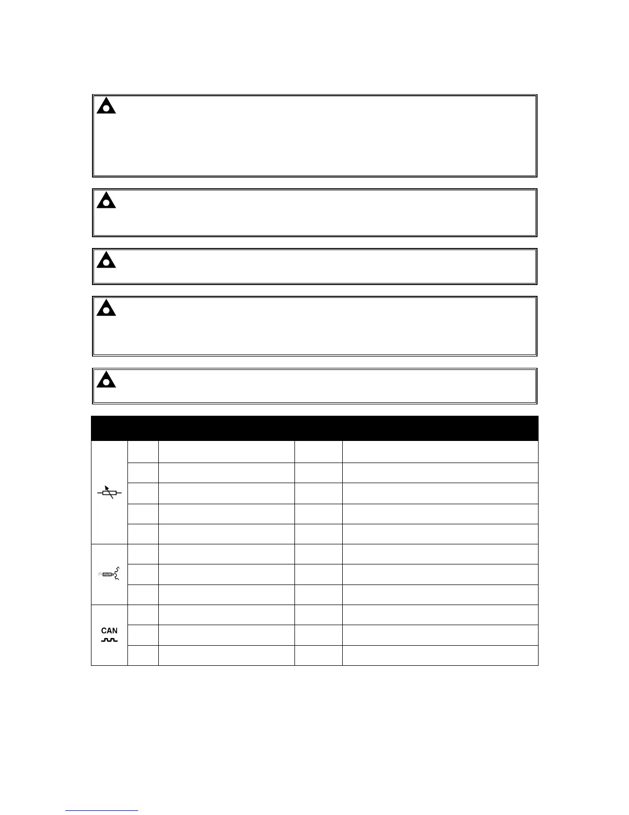
Pin
No
Description
Cable
Size
Notes
11 Sensor Common Return
0.5 mm²
AWG 20
Return Feed For Sensors
12 Oil Pressure Input
0.5 mm²
AWG 20
Connect To Oil Pressure Sensor
13 Coolant Temperature Input
0.5mm²
AWG 20
Connect To Coolant Temperature Sensor
14 Fuel Level Input
0.5 mm²
AWG 20
Connect To Fuel Level Sensor
15 Flexible Sensor Input
0.5 mm²
AWG 20
Connect To Additional Sensor (User Configurable)
16 Magnetic Pickup Positive
0.5 mm²
AWG 20
Connect To Magnetic Pickup Device
17 Magnetic Pickup Negative
0.5 mm²
AWG 20
Connect To Magnetic Pickup Device
18 Magnetic Pickup Screen Shield Connect To Ground At One End Only
19 CAN Port H
0.5 mm²
AWG 20
Use Only 120 Ω CAN Approved Cable
20 CAN Port L
0.5 mm²
AWG 20
Use Only 120 Ω CAN Approved Cable
21 CAN Port Screen Shield Use Only 120 Ω CAN Approved Cable

 Loading...
