4.3 CONTROL PUSH-BUTTONS
Icon Description
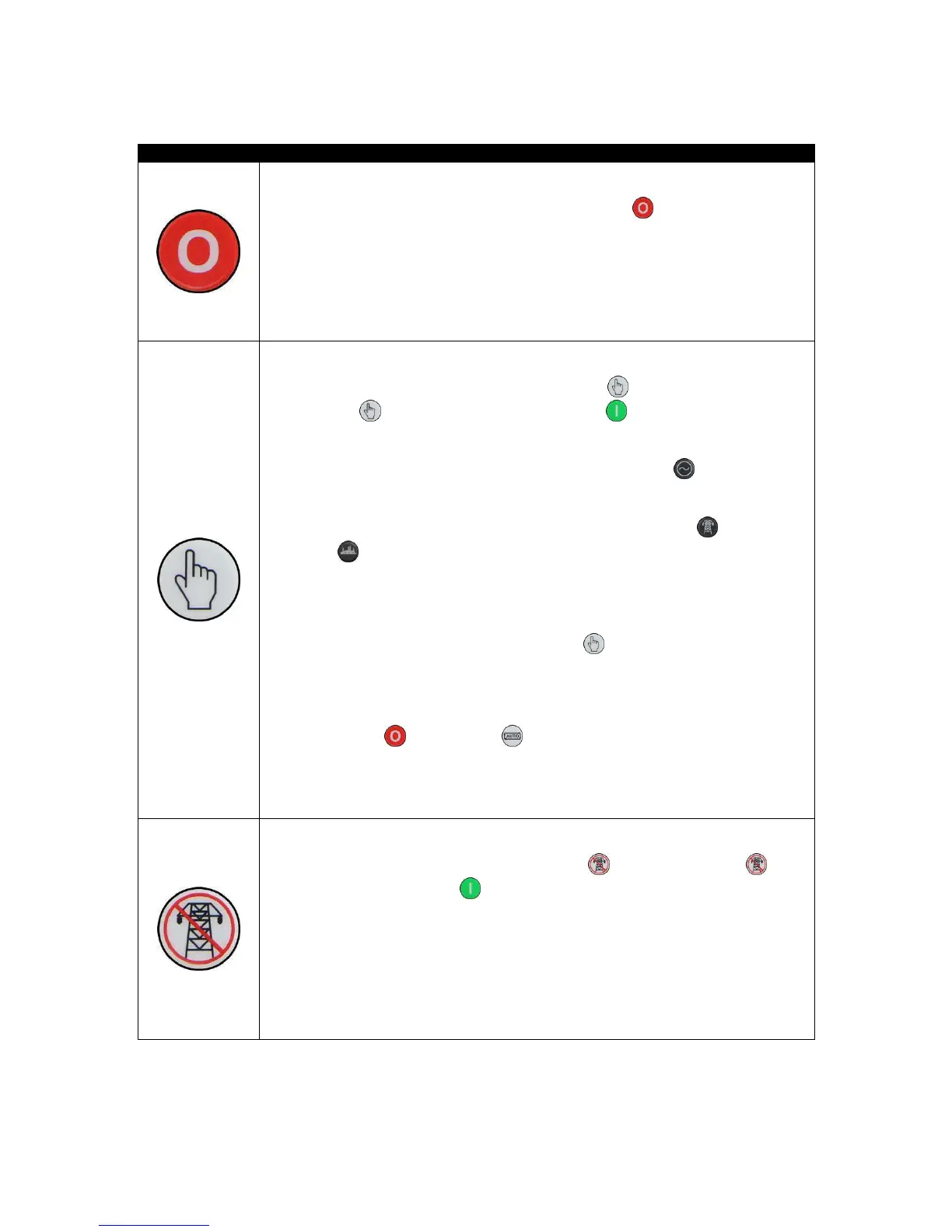
Stop / Reset Mode
This button places the module into its Stop/Reset Mode
. This clears any alarm
conditions for which the triggering criteria have been removed. If the engine is
running and the module is put into Stop mode, the module automatically instructs
the generator to unload (Close Generator and Delayed Load Output 1, 2, 3 & 4
become inactive (if used)). The fuel supply de-energises and the engine comes to
a standstill. Should any form of remote start signal be present when in Stop Mode
the generator remains at rest
Manual Mode
This button places the module into its Manual Mode
. Once in
Manual Mode
, the module responds to the Start button to start the
generator and run it off load.
To place the generator on load, use the Transfer to Generator
button. The
module automatically instructs the changeover device to place the generator on
load (‘Close Generator’ and Delayed Load Output 1, 2, 3 & 4 becomes active (if
used)). To place the generator off load, use the Transfer to Mains
or Open
Generator
buttons. The module automatically instructs the changeover device
to place the generator off load (Close Generator and Delayed Load Output 1, 2, 3
& 4 becomes inactive (if used)). Additional digital inputs can be assigned to
perform these functions.
If the engine is running off-load in Manual Mode
and a remote start signal
becomes present, the module automatically instructs the changeover device to
place the generator on load (‘Close Generator’ and ‘Delayed Load Output 1, 2, 3 &
4’ becomes active (if used)). Upon removal of the Remote Start Signal, the
generator remains on load until either selection of the
Stop/Reset Mode
or Auto Mode .
For further details, please see section entitled ‘Operation’ elsewhere in this
manual.
Test Mode (DSE6120 MKII Only)
This button places the module into its Test Mode
. Once in Test Mode , the
module responds to the Start
button to start the generator and run it off load.
Once the set has started the set automatically be placed on load (Close Generator
and Delayed Load Output 1, 2, 3 & 4 become active in order from lowest to
highest (if used)).
For further details, please see section entitled ‘Operation’ elsewhere in this
manual.

 Loading...
