3.1.1 DC SUPPLY, ESTOP INPUT, DC OUTPUTS & CHARGE FAIL INPUT
NOTE: When the module is configured for operation with an electronic engine, FUEL and
START output requirements may be different. For further details on connection to electronic
engines, refer to DSE Publication: 057-004 Electronic Engines And DSE Wiring
NOTE: For further details of module configuration, refer to DSE Publication: 057-224
DSE6110 MKII & 6120 MKII Configuration Software Manual.
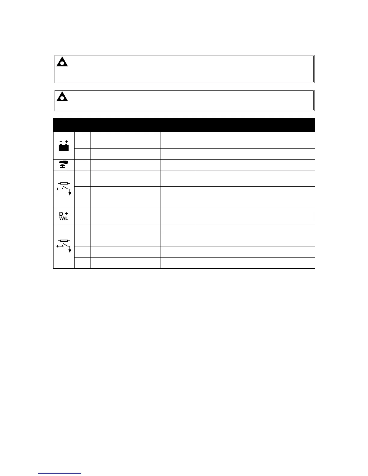
Pin
No
Description
Cable
Size
Notes
1
DC Plant Supply Input
(Negative)
2.5 mm²
AWG 13
2
DC Plant Supply Input
(Positive)
2.5 mm²
AWG 13
Supplies the module and DC Outputs A, B, C, D, E & F
3 Emergency Stop Input
2.5 mm²
AWG 13
Plant Supply Positive. Also supplies DC Outputs A & B.
(Recommended Maximum Fuse 20 A)
4 DC Output A (FUEL)
2.5 mm²
AWG 13
Plant Supply Positive from terminal 2.
10 A for 10 seconds, 5 A resistive continuous
Fixed as FUEL relay if electronic engine is not configured.
5 DC Output B (START)
2.5 mm²
AWG 13
Plant Supply Positive from terminal 2.
10 A for 10 seconds, 5 A resistive continuous
Fixed as START relay if electronic engine is not
configured.
6 Charge Fail / Excite
2.5 mm²
AWG 13
Do not connect to ground (battery negative).
If charge alternator is not fitted, leave this terminal
disconnected.
7 DC Output C
1.0 mm²
AWG 18
Plant Supply Positive from terminal 2. 2 A rated.
8 DC Output D
1.0 mm²
AWG 18
Plant Supply Positive from terminal 2. 2 A rated.
9 DC Output E
1.0 mm²
AWG 18
Plant Supply Positive from terminal 2. 2 A rated.
10 DC Output F
1.0 mm²
AWG 18
Plant Supply Positive from terminal 2. 2 A rated.

 Loading...
