2.4 TERMINAL SPECIFICATION
NOTE: For purchasing additional connector plugs from DSE, please see the section
entitled Maintenance, Spares, Repair and Servicing elsewhere in this document.
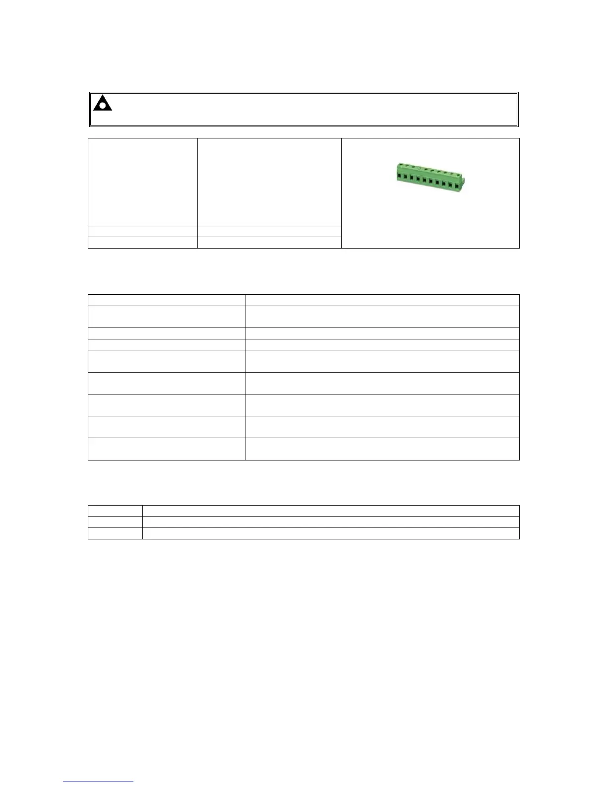
Connection Type
Two part connector.
• Male part fitted to
module
• Female part supplied in
module packing case -
Screw terminal, rising
clamp, no internal
spring.
Example showing cable entry and screw
terminals of a 10 way connector
Minimum Cable Size 0.5 mm² (AWG 24)
Maximum Cable Size 2.5 mm² (AWG 10)
2.5 POWER SUPPLY REQUIREMENTS
Minimum Supply Voltage 8 V continuous
Cranking Dropouts
Able to survive 0 V for 100 ms providing the supply was at
least 10 V before the dropout and recovers to 5 V afterwards.
Maximum Supply Voltage 35 V continuous (60 V protection)
Reverse Polarity Protection -35 V continuous
Maximum Operating Current
100 mA at 12 V
105 mA at 24 V
Maximum Standby Current
60 mA at 12 V
55 mA at 24 V
Maximum Current When In Sleep
Mode
40 mA at 12 V
35 mA at 24 V
Typical Power
(Controller On, Heater Off)
1.2 W to 2.4 W
Typical Power
(Controller In Standby, Heater Off)
0.7 W to 1.2 W
2.5.1 MODULE SUPPLY INSTRUMENTATION DISPLAY
Range 0 V to 70 V DC (note Maximum continuous operating voltage of 35 V DC)
Resolution

 Loading...
