GC-1F Installation Instructions and Reference Handbook
DEIF A/S Page 14 of 123
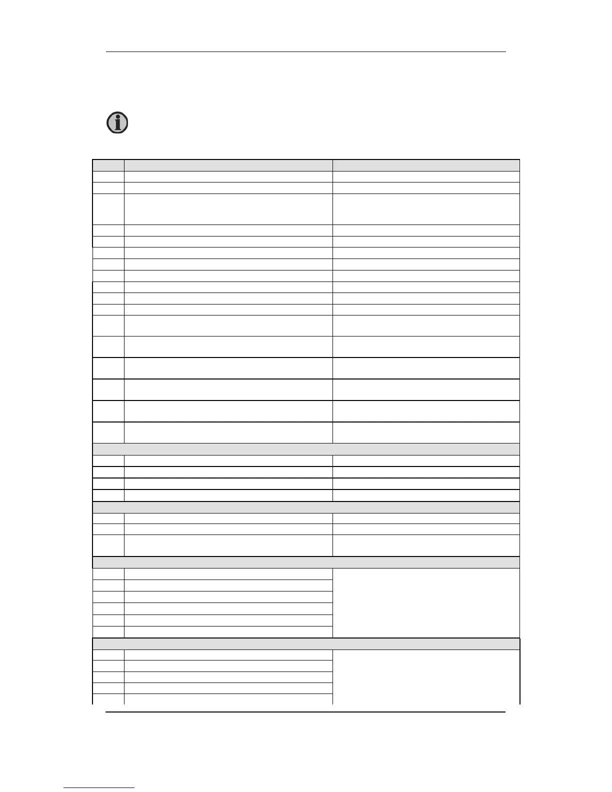
Terminal description
Term. Technical data Description
1 Power supply + Aux. supply
2 Power supply – GND
3-4 Status out/configurable. Contact ratings 1 A 24 V DC/
V AC Resistive
General status output for marine approvals**
Configurable only available from HW 1.05 and
sw 2.x.x
9 Common Common for term. 10 to 15
10 Digital input Start enable/configurable
11 Digital input Remote start/stop/configurable
12 Digital input Charge alternator D+ (running)/configurable
13 Digital input Configurable
14 Digital input Coolant temperature/configurable
15 Digital input Oil pressure/configurable
19 Common Common for emergency stop term. 20
20 Emergency stop and common for 21 to 23 Common for relay 21, 22 and 23 and input for
emergency stop*
21 Relay output 21. Contact ratings 2 A 30 V DC/V AC
(UL/cUL Listed: 1 A Resistive)
Start prepare/configurable. Function NO
22 Relay output 22. Contact ratings 2 A 30 V DC/V AC
(UL/cUL Listed: 1 A Resistive)
Starter (crank)/configurable. Function NO
23 Relay output 23. Contact ratings 2 A 30 V DC/V AC
(UL/cUL Listed: 1 A Resistive)
Run coil/configurable. Function NO
24-25 Relay output 24. Contact ratings 8 A 30 V DC/V AC
(UL/cUL Listed: 6 A Resistive)
Horn/configurable. Function NO
26-27 Relay output 26. Contact ratings 8 A 30 V DC/V AC
(UL/cUL Listed: 6 A Resistive)
Alarm/configurable. Function NO
Multi-functional inputs
5 Common Common for term. 6 to 8
6 RMI1/0(4) to 20 mA/binary input Fuel level/configurable
7 RMI2/0(4) to 20 mA/binary input Oil pressure/configurable
8 RMI 3/0(4) to 20 mA/binary input Water temp./configurable
Tacho RPM input
16 RPM input (MPU) Magnetic pickup/tacho generator
17 RPM-GND Common for RPM input
18 RPM input (W/L) Magnetic pickup. PNP, NPN or charge alternator
W terminal
3-phase generator voltage input
33 Gen. voltage L1
Generator voltage and frequency
34 Gen. neutral
35 Not used, must not be connected
36 Gen. voltage L2
37 Not used, must not be connected
38 Gen. voltage L3
3-phase generator current input
39 Gen. current L1, s1
Generator current
40 Gen. current L1, s2
41 Gen. current L2, s1
42 Gen. current L2, s2
43 Gen. current L3, s1
For the relay outputs the following terms will be used:
NO means Normally Open.
NC means Normally Closed.
Com. means common terminal for the individual relay.

 Loading...


