GC-1F Installation Instructions and Reference Handbook
DEIF A/S Page 23 of 123
Communication
Wiring instructions
Cable
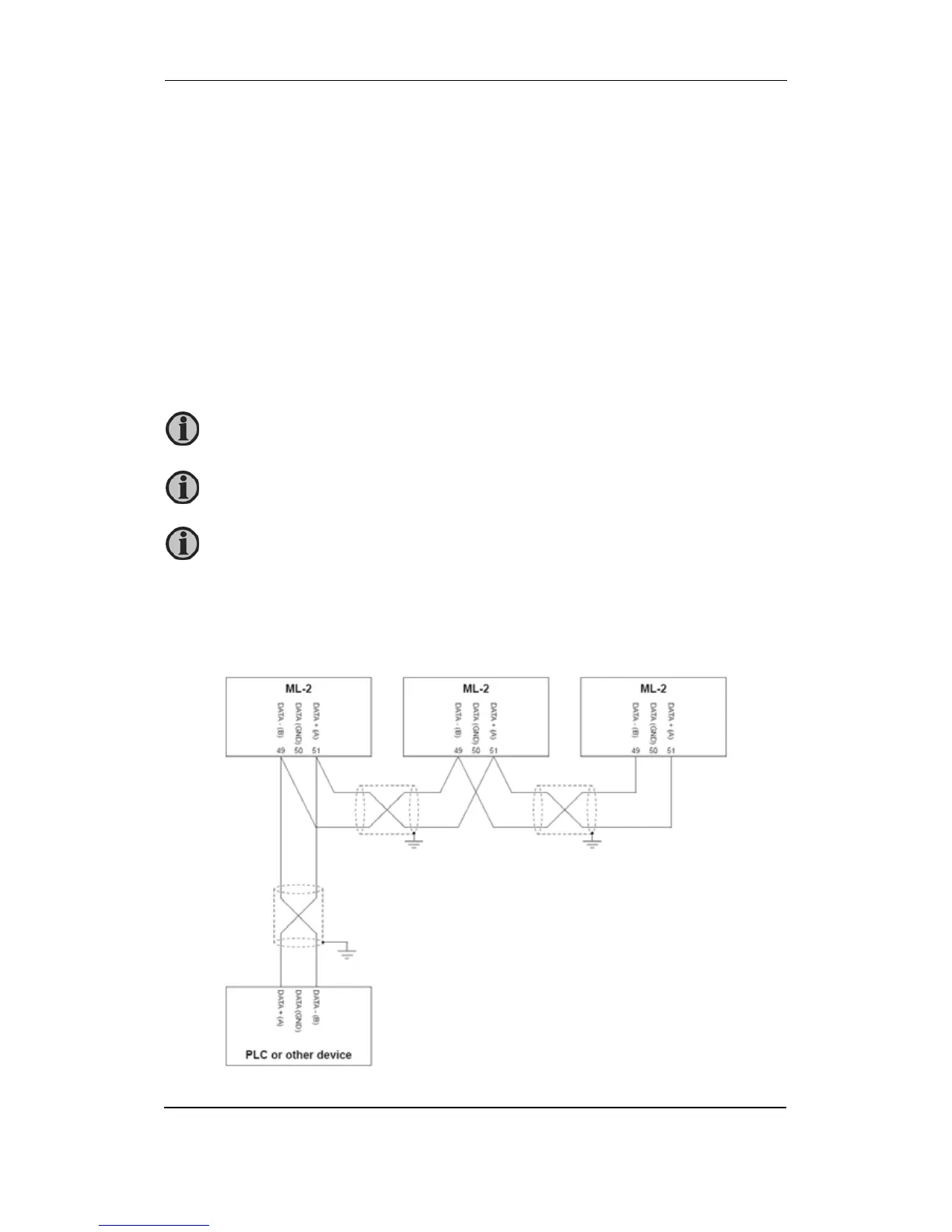
Belden 3106 A or equivalent. 22 AWG (0.324 mm
2
) shielded twisted pair, min. 95 % shield
coverage.
Cable shield
Connect the cable shield to earth at one end only.
GND terminal connection
In case of communication problems, the GND terminals of the GC-1F unit and the external
device can be linked together using a third wire.
CAN bus termination resistor
The size of the terminating resistors should be 120 1 %, 0.5 W resistor.
Option H2, Modbus RTU
Connection with 2-wire shielded cable (recommended):
Never connect the GND terminal to earth directly or through the shield!
If the GND terminal is connected to a PLC or other device, the GND connection
of this device must be isolated from earth!
Maximum length of the CAN bus line is 400 m.
 Loading...


