GC-1F Installation Instructions and Reference Handbook
DEIF A/S Page 13 of 123
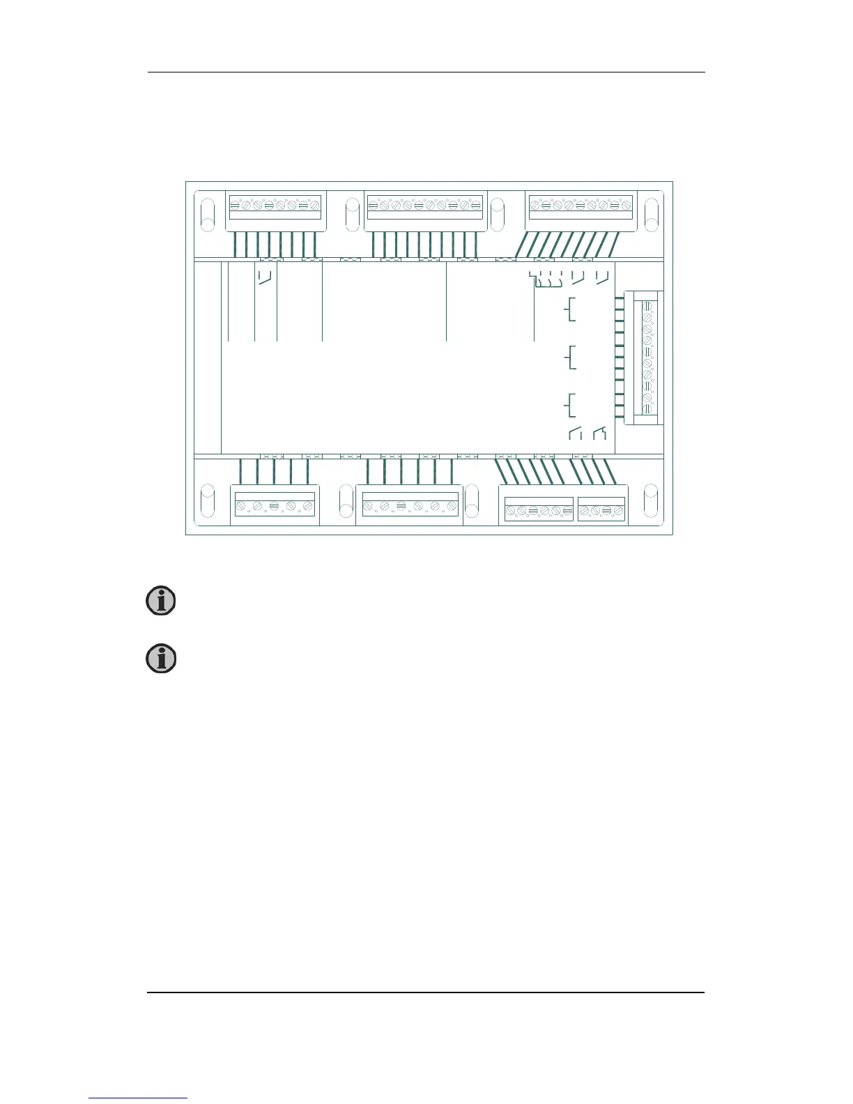
Terminals
Unit rear view
The RJ11 connector for the PC connection interface box is placed on the side of
the unit.
1 2 3 4 5 6 7 8 9 10 11 12 13 14 15 16 17 18 19 20 21 22 23 24 25 26 27
28 29 30 31 32 33 34 35 36 37 38
L1 N L2 NA L3 L1 N NA L2 NA L3
Mains voltage
Gen Voltage
+ 0 1 2 3
R21 R22 R23
com
Power
supply
Status
config
Multi func-
tional input
1 2 3 4 5 6
com
com
Input
R24 R26
Binary inputs Emergency
stop
45 46
39 40 41 42 43 44
L1
Gen Current
L2
L3
49
50
51
52
53
54
55
56
57
58
59
Can L
GND
Can H
Can 1 J1939
Option H5
B(-)
GND
A(+)
Modbus
RS485
Option H2
Option H8/X4
Can 2
Can H
GND
Can L
47 48
Term. 3-4, status relay is only configurable in HW 1.05 and SW 2x.x.
 Loading...


