GC-1F Installation Instructions and Reference Handbook
DEIF A/S Page 60 of 123
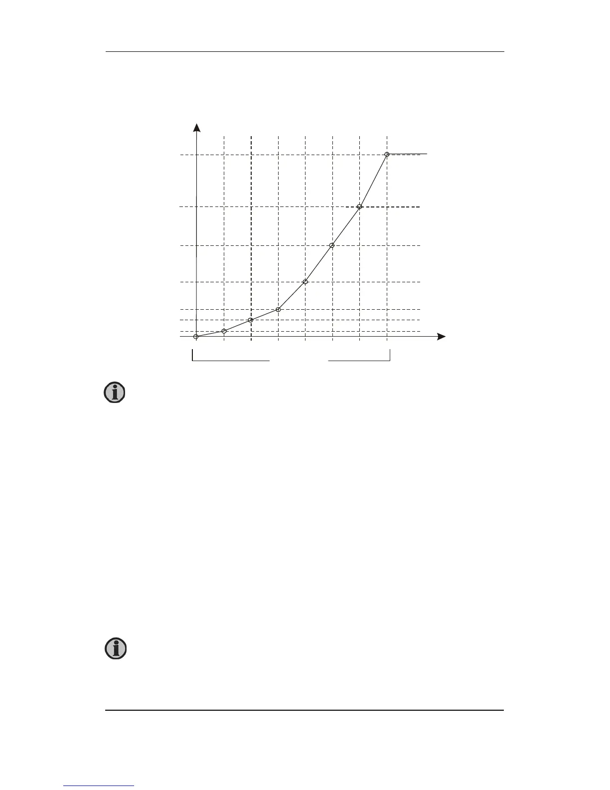
Illustration of configurable inputs
Configuration
The eight curve settings for the configurable VDO inputs cannot be changed in the display, but
only in the PC utility software.
Binary input with wire break detection
The binary inputs are based on the VDO inputs, that is if a VDO input is selected, the binary
input cannot be chosen, and vice versa. When selected as multi-functional inputs, the three
VDO inputs can be changed into binary inputs with wire break detection. The wire break
detection is selectable (ON/OFF) and based on the VDO inputs using a 100 Ohm resistor across
the monitored switch. The resulting function is:
R < 20 Ohm = Switch closed
30 < R < 140 Ohm = Switch open, cable OK
150 Ohm < R = Wire break
The setting of the alarm input is carried out in the same way as the setting of the standard binary
input. The texts can be changed in translation.
1 2 3 4 5 6 7 8
Set point 1
Set point 2
Set point 3
Set point 4
Set point 5
Set point 6
Set point 7
Set point
Set points
Resistance (Ohm)
Value (bar/psi/Cel/F
All Y and X axis values can be adjusted in the entire range.
Binary input with wire break can be used as 3 state input switch in M-Logic.
 Loading...


