V0505, 3.12
3.h
Auxiliary axis . . . . . . . . . . . . . . . . . . . . . . . . . . . . . . . . . . . . . . . . . . . . .R/Z/Aux.
If you have one or more auxiliary axes (for instance a R-axis, Z-axis or part support) the
parameters of these axes appear here.
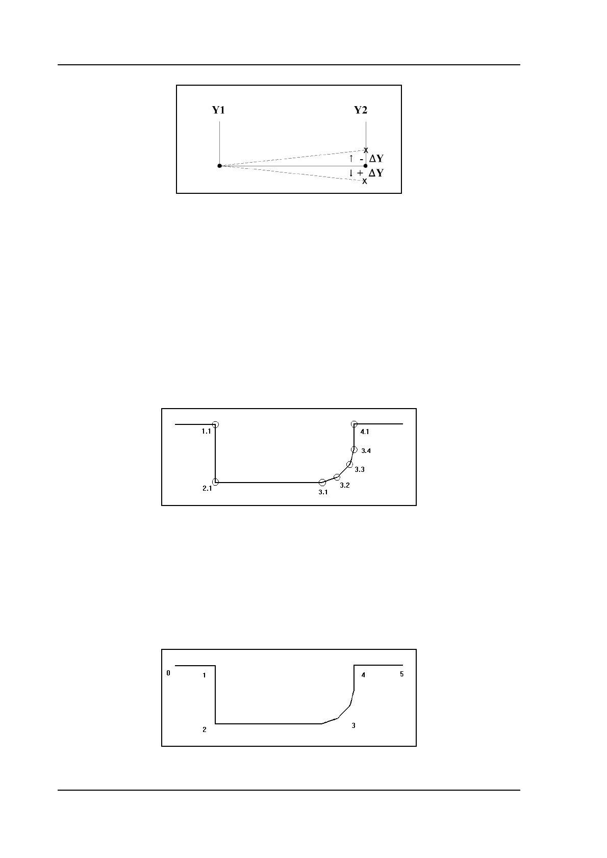
Angle number . . . . . . . . . . . . . . . . . . . . . . . . . . . . . . . . . . . . . . . . . . . . .AN
The rank number of this angle, when counted from left to right through the product pro-
file (figure 4.j). The digit before the dot describes this rank number, the digit after the dot
descibes the rank number of this bend in case of a bumping sequence.
In case of a normal angle, the bumping number should always be 1. In the case of a
radius bend, all bends in the bumping sequence should have the same angle number but a
different bumping number. Programming a radius bend in this manner will allow for
bumping correction in the production mode.
3.i
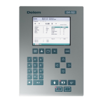
Backgauge number . . . . . . . . . . . . . . . . . . . . . . . . . . . . . . . . . . . . . . . .XN
A backgauge number refers to a certain spot of the product, that can be placed against the
backgauge during bending. Such a spot is either a product end or an angle. The back-
gauge numbers in the product are counted from left to right, starting with 0 (see figure
4.k). For each bend you must program here which spot must be placed against the back-
stop. If the plate must rest on the backgauge finger, add 100 to the XN value. For each
next lay-on position, add another 100 to the backgauge value (200, 300, etc.).
3.j