V0505, 7.14
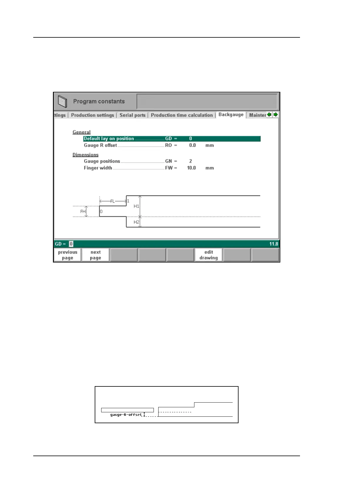
7.8. Backgauge dimensions
With these finger dimensions the R-axis movement and work/backgauge collision can be com-
puted.
7.m
Gauge positions . . . . . . . . . . . . . . . . . . . . . . . . . . . . . . . . . . . . . . . . . . .GN =
The number of possible gauge positions (max. 4). When this parameter is changed, a new
pop-up window with finger geometry appears. There the finger dimensions can be pro-
grammed.
Default lay on position . . . . . . . . . . . . . . . . . . . . . . . . . . . . . . . . . . . . . .GD =
Default gauge lay on position when lay on is selected during the graphical bendsequence
programming.
Default value=0, not lay on.
Gauge R offset . . . . . . . . . . . . . . . . . . . . . . . . . . . . . . . . . . . . . . . . . . . .RO =
An offset value for the R-axis can be set if the backgauge is positioned against the sheet
edge and the X-axis position is outside the die safety zone.
7.n
A negative value gives a lower backgauge position. This offset is only valid for gauge
position 0.