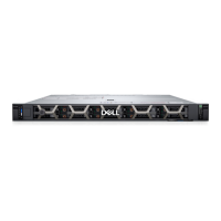
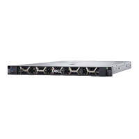
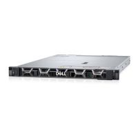
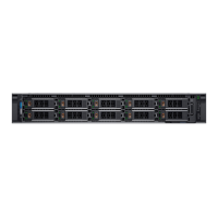
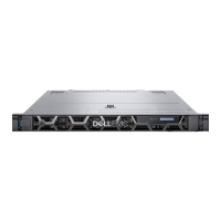
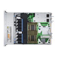
Figure 53. 4 x 3.5-inch drive backplane
1. BP_SIG_PWR_1 (backplane power and signal cable to system board)
Figure 54. 8 x 2.5-inch drive backplane
1. DST_PB2 (PCIe/NVMe connector) 2. DST_SB1(backplane to front PERC)
3. DST_PA2 (PCIe/NVMe connector) 4. BP_PWR_1 (backplane power and signal cable to system
board)
5. DST_PB1 (PCIe/NVMe connector) 6. DST_SA1(PCIe/NVMe connector)
7. PWR_CTRL 8. DST_PA1 (PCIe/NVMe connector)
Figure 55. 10 x 2.5-inch drive backplane
1.
DST_SB1 2. DST_PA3 (PCIe/NVMe connector)
3. P8 4. DST_PB2 (PCIe/NVMe connector)
5. BP_PWR_1 (backplane power and signal cable to system
board)
6. PWR_CTRL
7. DST_PA2 (PCIe/NVMe connector) 8. DST_SA1 (PERC to backplane)
9. DST_PB1 (PCIe/NVMe connector) 10. DST_PA1 (PCIe/NVMe connector)
Figure 56. 14 x E3.S drive backplane
1.
BP_DST_PB2 2. BP_DST_PA2
3. BP_DST_PB1 4. BP_DST_PA1
5. BP_PWR_1 (backplane power and signal cable to system
board)
86 Installing and removing system components

 Loading...
