Chapter 8 Logic Instructions
Output Update Timing
Parameter Name
Timing for changing to TRUE Timing for changing to FALSE
Done
When the writing of the parameter
values is finished.
When Execute changes from TRUE to
FALSE after the instruction execution is
Busy
When Execute changes to TRUE
When Done changes from FALSE to
TRUE
When Error changes to TRUE.
Active
When the instruction execution begins
When Error changes to TRUE.
When Done changes from FALSE
Error
When an error occurs in the instruction
execution or the input parameters for
the instruction are illegal.
When Execute changes from TRUE to
FALSE.
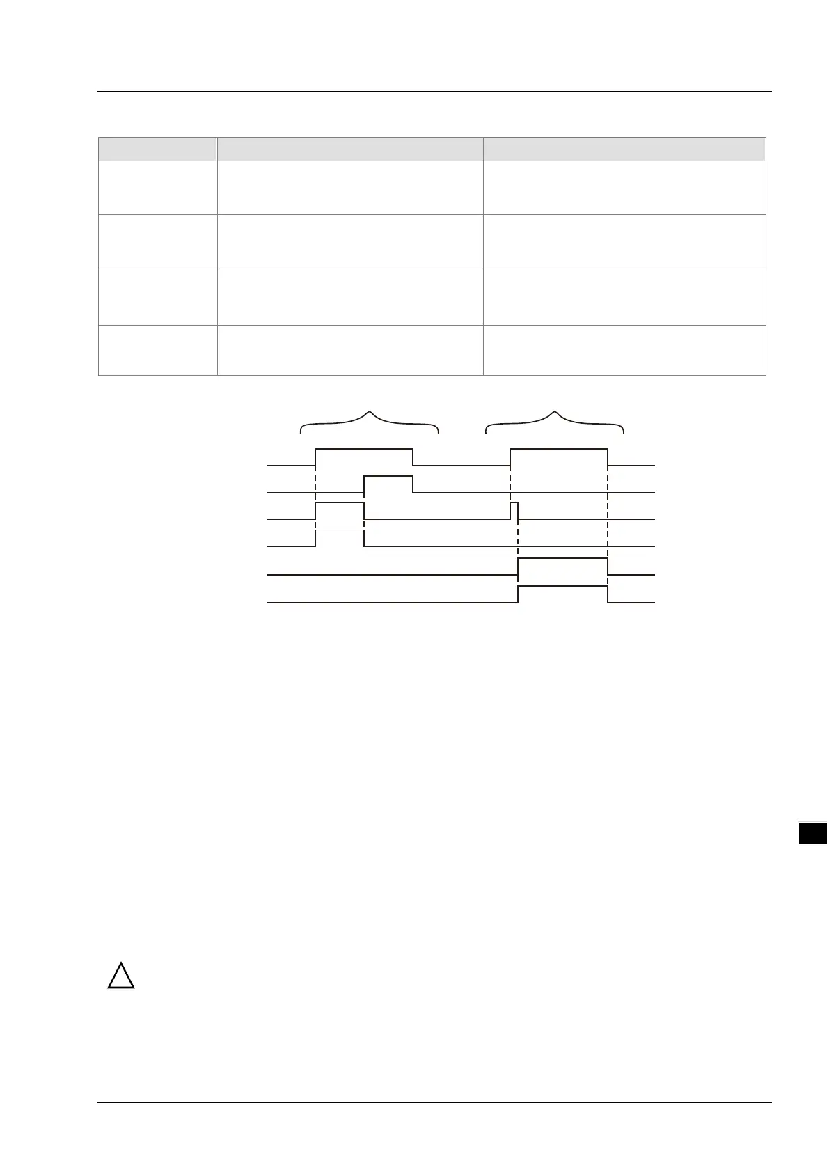
Output Update Timing Chart
Execute
Done
Busy
Active
Error
ErrorID
Case 1 Case 2
Case 1: When Execute changes from FALSE to TRUE, Busy and Active change to TRUE. One period
later, Done changes to TRUE. Meanwhile Busy and Active changes from TRUE to FALSE. After
Execute changes from TRUE to FALSE, Done changes from TRUE to FALSE.
Case 2: When an error occurs as Execute changes from FALSE to TRUE, Error changes from FALSE to
TRUE and ErrorID shows corresponding error codes. Error changes from TRUE to FALSE and
the value in ErrorID is cleared to 0 after Execute changes from TRUE to FALSE.
Function Explanation
The TO instruction is used to write data to the specified CR registers of the left-side module and right-side
module.
The positions of left-side and right-side modules are specified by StationID. The StationID range of right-side
module is 0~7. 0 represents the first extension analog module at the right side. 7 is the eighth extension
analog module at the right side. The StationID range of left-side module is 100~107. 100 is the first extension
module at the left side. 107 is the eighth extension analog module at the left side. If StationID value exceeds
the specified range for left-side and right-side modules, an error will occur in execution of the instruction.
If the instruction is used to write values to multiple CR registers, DesPtr need be defined as the N
th
element of
the array. Then multiple values will be written to multiple CR registers by writing the N
th
element value to the
first CR, the N+1
th
element value to the second CR and so on after execution of the instruction.
Refer to the following program examples for more details on the usage.
Maximum 8 extension modules are connectable to the left side and Maximum 8 special modules are
connectable to the right side of DVP15MC11T. The right-side digital modules have no position number. For
example, if DVP04AD-S, DVP16SP11T and DVP04DA-S are connected to the right side of DVP15MC11T one
after another, the StationID value of DVP04AD-S is 0 and the StationID value of DVP04DA-S is 1.
8-207