DVP15MC11T Operation Manual
Case 4: Done changes to TRUE when the instruction execution is completed after Execute changes
from TRUE to FALSE in the course of execution of the instruction. Meanwhile, Busy and Active
change to FALSE and one cycle later, Done changes to FALSE.
Function
1. According to the set homing mode, the MC_Hme instruction is used for connecting the home switch
and positive limit switch or negative limit switch to the external input points of the servo drive so as
to achieve the homing function.
2. For real axes, the homing mode and phase-1 speed and phase-2 speed of the homing are set in the
software axis parameter setting. See Appendix D for details on homing modes. For virtual axes, the
homing mode can only be set to mode 35.
3. The instruction can be executed only while the axis is in Stanstill state. Otherwise, an error will
occur.
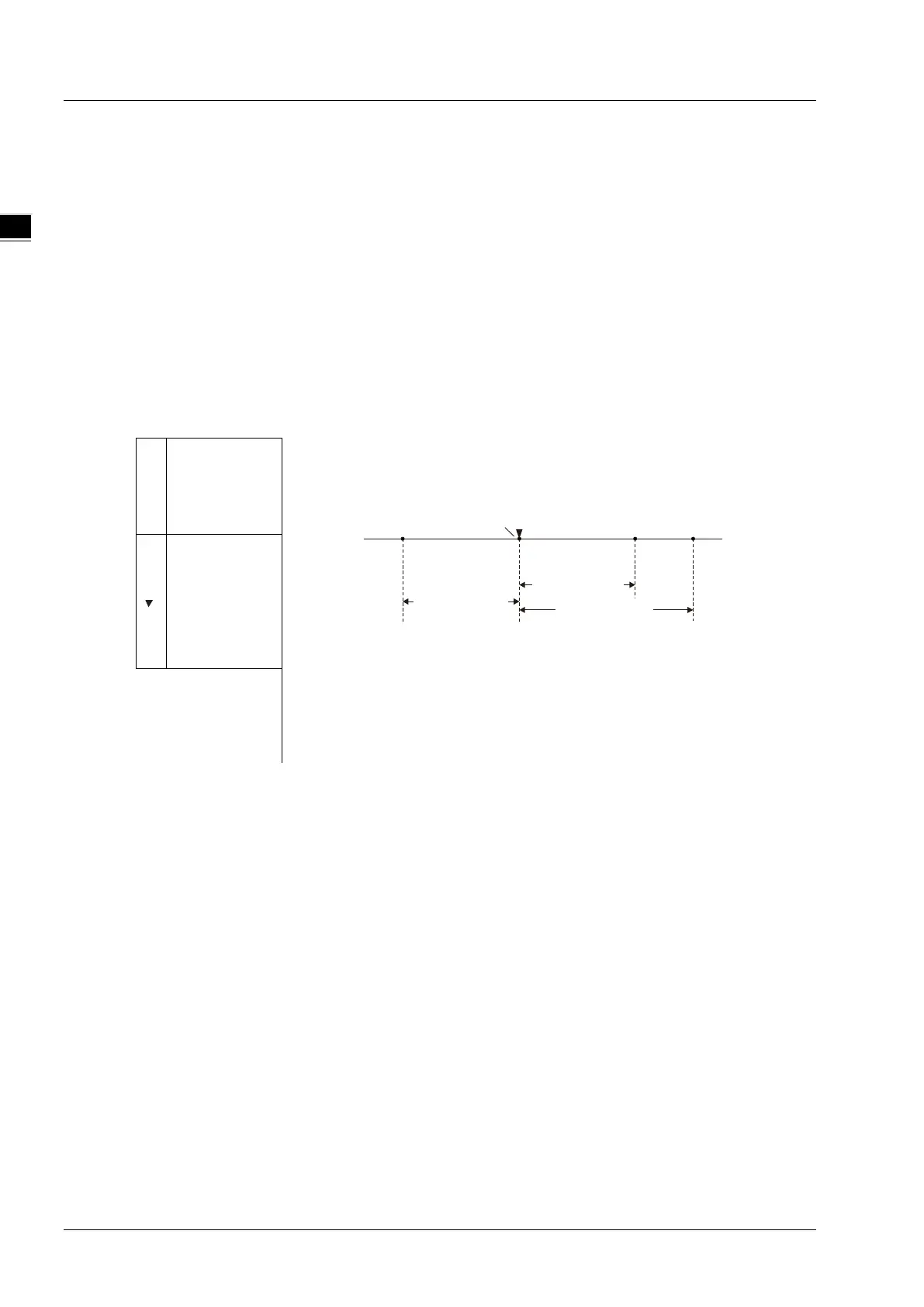
4. Position parameter defines the offset between the mechanical zero point and servo reference zero
point as the figure below:
A
zero point,
where the
photoelectric
sensor is.
Position
value, the servo will eventually stop at the
mechanical point A under the control of this instruction. But the reference
zero point of the servo position will change as shown below.
As Position=10000, the reference zero point of the servo position is point
D and point A position is 10000;
As Position=-15000, the reference zero point of the servo position is point
C and point A position is -15000;
As Position=-10000, the reference zero point of the servo position is
point B and point A position is -10000.
is where the
servo is after
execution of
the
instruction is
Programming Example
Select an appropriate homing mode via the positions of the mechanism and photoelectric switch. When Hom
_Ex changes from FALSE to TRUE, the motion controller controls the servo motor to rotate and drive the
mechanism to return to the mechanical zero point position A.
Position=-15000
A
Position=10000
Position= -10000
0
00
+
–
C
BD
11-16