Chapter 12 Troubleshooting
1
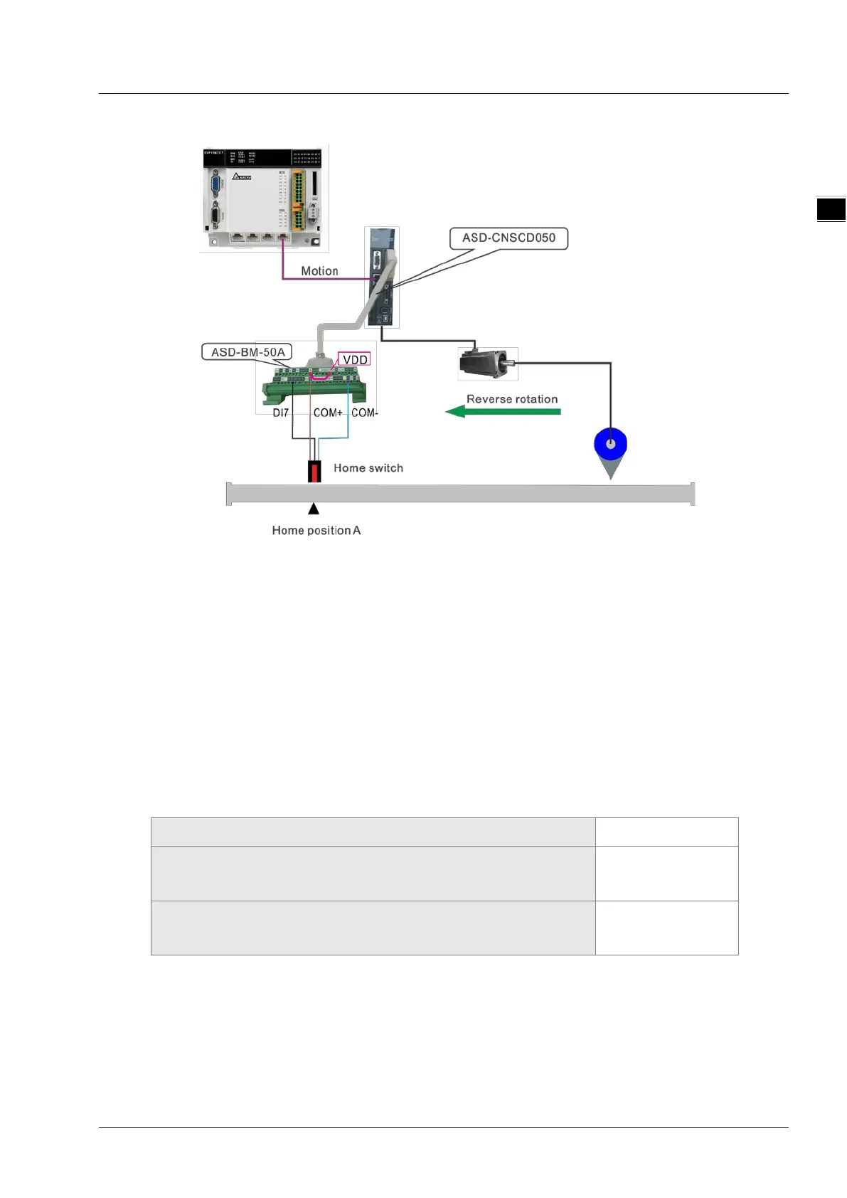
Hardware wiring
Note:
During wiring, COM+ and VDD must be shorted.
Of the photoelectric switch, the brown terminal (24V+) is connected to COM+, the blue terminal
(0V) is connected to COM- and the black terminal (Signal cable) is connected to DI7.
The DI7 function is set to the home switch, i.e. P2-16 is set to 124.
Homing mode selection
It can be seen from the hardware wiring figure that the mechanism regards the home switch position
as the mechanical zero point position A. The home switch is OFF before searching for the home.
While the mechanism is searching for the home point, the servo rotates reversely at beginning and
homing mode 21 can be selected to achieve the homing.
The settings for homing in the corresponding axis parameters are as follows.
Homing mode
21
The first-phase speed (the speed for finding the home switch, Unit:
r/m)
100
The second-phase speed (The speed from finding the home switch
to reaching the mechanical zero point, Unit: r/m)
10
Note: The set axis parameters are valid after being downloaded.
11-17