Revision February, 2017 3-1
Chapter 3 Wiring
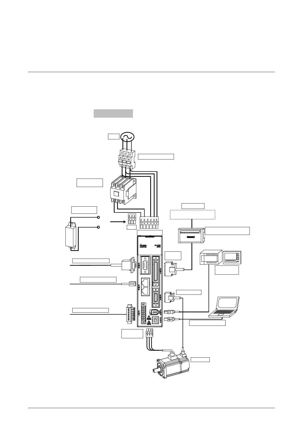
This chapter provides information on wiring ASDA-A2 series products, the descriptions of I/O
signals and gives typical examples of wiring diagrams.
3.1 Connections - 220V series
3.1.1 Connecting to Peripheral Devices
For full-closed loop or linear scale connection
CN5: For ASDA-A2-L, -M, -U (Please refer to
the description of section 1.2.2)
CN7: For ASDA-A2-U only (Please refer to the
description of section 1.2.2)
CN6: For ASDA-A2-M only (Please refer to the
description of section 1.2.2)
CN1 I/O
Connector
Use MODBUS
communication to support
RS-485/RS232
1. Connect to personal computer via USB cable
2. Use ASDA-SOFT for tuning, parameter setting
and control.
Transmit the signal from CN1
50pin to the controller via this
block module.
It can connect to Delta PLC controller
or other brands of NC controllers.
The returned regenerative power generated
when braking may result in damage. Thus,
external resistor is recommended. Connect
the external resistor to P and C, and ensure
an open circuit between P and D. When
applying internal resistor, ensure the circuit
is close between P and D, and the circuit is
open between P and C.
100W~1.5kW Single-/Three-phase 200~230V
2kW~15kW Three-phase 200~230V
Installing a NFB can prevent excessive current may
arise due to short-circuit or flow when power on and
off, so as to avoid the damage on the servo drive
P
C
Power
No Fuse Breaker (NFB)
Host Controller
Terminal Block Module (ASD-BM-50A)
(Option)
P,D,C
Electrom agnetic
Conta ctor (MC)
Regenerative
Resistor (Option)
CN5 Connector (Option)
CN6 Connector (Option)
CN7 Connector (Option)
CN2 Connector
CN4 Connector (Option)
Servo Motor
Motor power
output
CN3 Connector
(Option)
L1c,L2c,Θ,R,S,T
 Loading...
