5-25
5
Installation and Wiring
WARNING:
%HIRUHVWDUWXSRIWKHSDUDOOHOXQLWVTXDOL¿HGVHUYLFHSHUVRQQHOPXVWVHWHDFK
UPS’s ‘Parallel Group ID’ (1 or 2) and ‘Parallel ID’ (1~8) through the LCD.
Otherwise, the parallel UPSs cannot be started. Please refer to 7.10.5 Parallel
Setting.
y
Dual Input (Parallel Units)
When there are two AC power sources, parallel units’ wiring procedures are as follows.
1
Follow 6LQJOH,QSXW'XDO,QSXW0RGL¿FDWLRQ to modify the UPS from single
input to dual input.
2
Refer to the procedures
1
~
8
stated in the section of Single Input (Single
Unit).
3
Connect the main AC source, bypass source, output and external battery cabinet’s
cables to each UPS. There are two types of wiring, top wiring and bottom wiring.
Please refer to the following.
Figure 5-21: Single Unit Dual Input Top Wiring Diagram_ Step 1
Figure 5-22: Single Unit Dual Input Top Wiring Diagram_ Step 2
Figure 5-23: Single Unit Dual Input Bottom Wiring Diagram_ Step 1
Figure 5-24: Single Unit Dual Input Bottom Wiring Diagram_ Step 2
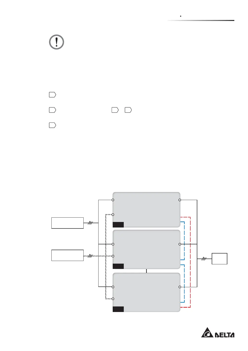
Figure 5-27: Parallel Units Dual Input Wiring Diagram
5.6 External Battery Cabinet Connection Warnings
UPS 1
UPS 2
UPS 8
Parallel Port
Parallel Port
Parallel Port
Parallel Port
Parallel Port
Parallel Port
3Ø4W
3Ø4W
3Ø4W
Parallel CableParallel Cable
Parallel CableParallel Cable
Loads
Main AC Source
Bypass Source
AC Input
Terminals
Bypass Input
Terminals
Bypass Input
Terminals
Bypass Input
Terminals
AC Input
Terminals
AC Input
Terminals
UPS Output
Terminals
UPS Output
Terminals
UPS Output
Terminals
Daisy
Chain
Method
(Figure 5-27: Parallel Units Dual Input Wiring Diagram)
 Loading...