4-12
Ultron HPH Series
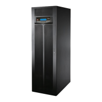
(Figure 4-13: Location of Master and Backup Parallel Communication Cards
and their LED Indicators)
DISPLAY
REPO
NC NO
EXT. BATT
TEMP.
BT1 BT2
EXT.SWITCH
STATUS
S1 S2
S3 S4
BT3
BT4
O/P DRY
CONTACT
USB RS-232
P1 P2 P3
P4
P5 P6
I/P DRY
CONTACT
P1 P2
BATT.
START
BATT.
START
P3
P4
PAR ALL EL
PARALLEL
Master Parallel Communication
Card’s LED Indicator
Master Parallel
Communication Card
Backup Parallel Communication
Card’s LED Indicator
Backup Parallel
Communication Card
If both cards work normally, the master parallel communication card’s LED indicator will
illuminate green and the backup parallel communication card’s LED indicator will illuminate
yellow.
If one card works normally and the other works abnormally, the normal card’s LED indicator
will illuminate green and the abnormal card’s LED indicator will illuminate red.
'XULQJLQLWLDOL]DWLRQSURFHVVERWKFDUGV¶/('LQGLFDWRUVÀDVK\HOORZ
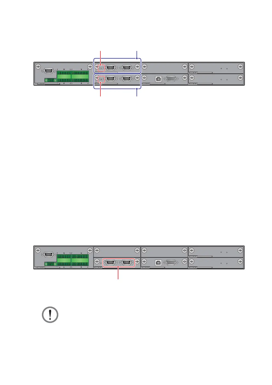
4.1.8 Parallel Ports
The parallel ports (see Figure 4-14) are used to connect parallel UPSs to increase the
system capacity and redundancy. With the provided parallel cable, up to eight UPS units
with the same capacity, voltage and frequency can be paralleled. To enhance parallel
reliability, please adopt Daisy Chain method (see Figure 5-25 & Figure 5-27) to execute
SDUDOOHOFRQ¿JXUDWLRQ
DISPLAY
REPO
NC NO
EXT. BATT
TEMP.
BT1 BT2
EXT.SWITCH
STATUS
S1 S2
S3 S4
BT3
BT4
O/P DRY
CONTACT
USB RS-232
P1 P2 P3
P4
P5 P6
I/P DRY
CONTACT
P1 P2
BATT.
START
BATT.
START
P3
P4
PAR ALL EL
Parallel Ports
(Figure 4-14: Location of Parallel Ports)
WARNING:
The provided parallel cable is placed in the accessory package. Using other types
of cables to connect the parallel UPSs may cause parallel failure, malfunctions
and accidents.
 Loading...