3-5
3
Operation Modes
3.1.4 Manual Bypass Mode_ Single Input_ Single Unit
When the UPS needs maintenance, you can manually switch the UPS to manual bypass
mode. To let the UPS run in manual bypass mode, please follow the procedures below:
1
&RQ¿UPWKDWWKHE\SDVV$&VRXUFHDQGWKH676PRGXOHDUHQRUPDO
2
Press the LCD’s ON/ OFF button ( ) once and the ‘POWER OFF?’ screen will pop
XSWRDVN\RXLI\RXZDQWWRSRZHURႇWKH836¶VLQYHUWHU3OHDVHVHOHFWµYES’.
3
Turn on the Manual Bypass Switch (Q3).
4
7XUQRႇWKH%\SDVV6ZLWFK4
5
7XUQRႇWKH,QSXW6ZLWFK4DQG2XWSXW6ZLWFK4
6
7XUQRႇHDFKH[WHUQDOEDWWHU\FDELQHW¶VEUHDNHU4
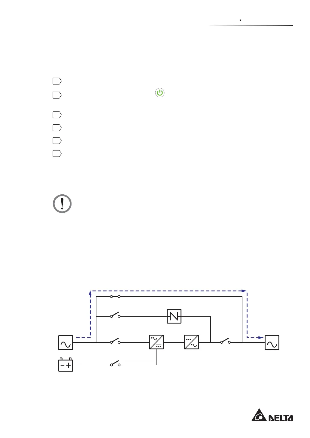
,QPDQXDOE\SDVVPRGHDOOSRZHULQVLGHWKH836LVFRPSOHWHO\FXWRႇDQGPDLQWHQDQFH
personnel can perform maintenance safely. Please see Figure 3-4 for manual bypass mode
GLDJUDP'XULQJPDQXDOE\SDVVPRGHWKH836¶VWULFRORU/('DQG/&'DUHERWKRႇ
WARNING:
1. In manual bypass mode, make sure that all of the switches and breakers (except
the Manual Bypass Switch (Q3)) are in the OFF position before working on the
UPS’s internal circuits. This avoids electric shock.
$IWHUWKHSRZHULQVLGHWKH836LVFRPSOHWHO\FXWRႇWKHUHLVQRKLJKYROWDJH
inside the UPS except the wiring terminals and the Manual Bypass Switch (Q3).
Do not touch the wiring terminals and the Manual Bypass Switch (Q3) during
UPS maintenance process to avoid electric shock.
'XULQJPDQXDOE\SDVVPRGHWKH836¶VLQSXWSRZHULVFRPSOHWHO\FXWRႇDQG
the connected critical loads are not protected.
MAIN LOAD
Q1
Q2
Q4
Q3
Batteries
Rectifier Inverter
Static Switch
Q5
(Figure 3-4: Manual Bypass Mode Diagram_ Single Input Single Unit)
 Loading...