3-7
3
Operation Modes
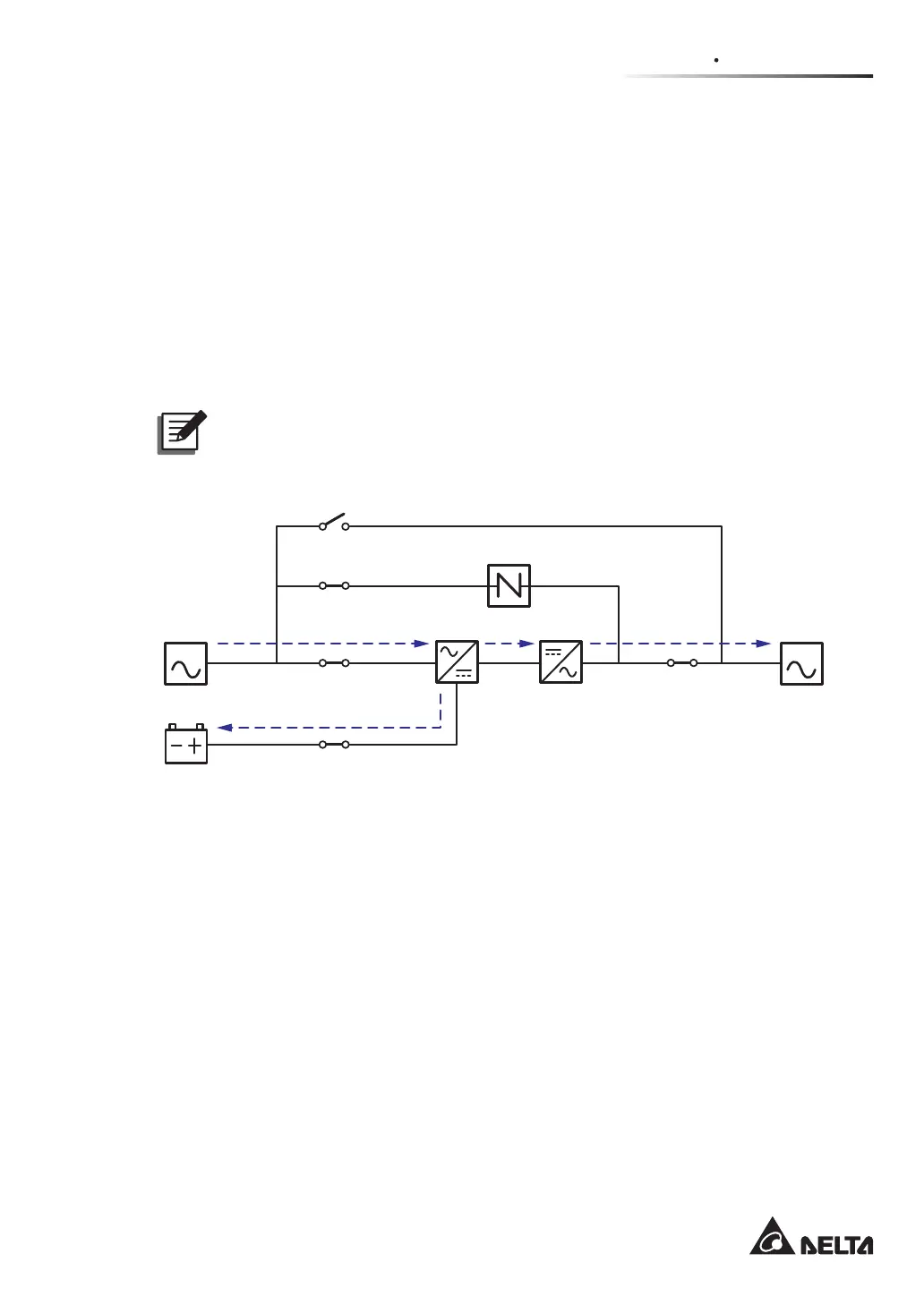
3.1.6 Frequency Conversion Mode_ Single Input_ Single Unit
To activate frequency conversion mode, please refer to 6.2.6 Frequency Conversion
Mode Start-up Procedures, 7.6 Main Screen and 7.10.2 Mode Setting.
After the UPS is manually set in frequency conversion mode, the inverter will automatically
VHOHFW+]RU+]DVWKH¿[HGRXWSXWIUHTXHQF\$IWHUWKHRXWSXWIUHTXHQF\LVGHWHUPLQHG
the system will automatically disable the bypass function. Please note that, once the
inverter shuts down, there is no bypass output. For the diagram of frequency conversion
mode, please see Figure 3-6. During frequency conversion mode, the UPS’s tri-color LED
illuminates green and the text ‘Frequency Conversion’ appears in the upper right corner of
the screen.
NOTE:
During frequency conversion mode, once the inverter shuts down, there is no
bypass output.
(Figure 3-6: Frequency Conversion Mode Diagram_ Single Input Single Unit)
MAIN LOAD
Q1
Q2
Q4
Q3
Batteries
Rectifier Inverter
Static Switch
Q5
 Loading...