7-3
7
LCD Display & Settings
NOTE:
1.
*
1
means that the ADMINISTRATOR password is needed. For password information,
please refer to 7.5 Password Entry.
2. The information on the LCD screen presented in 7. LCD Display & Settings, including
UPS operation mode, machine number, date, time, total number of alarms, load %,
battery remaining time, user login or administrator login, are for reference only. The
actual screen of display depends on operation situation.
3. For how to turn on the touch panel, please refer to 7.2 How to Turn on the LCD and 7.3
ON/ OFF Button.
7.2 How to Turn on the LCD
1
To turn on the LCD, please follow the steps below:
a. Turn on the Input Switch (Q1). After that, the LCD will be on and LCD initial screen
(Figure 7-3) will appear; or
b. Turn on the Bypass Switch (Q2). After that, the LCD will be on and LCD initial
screen (Figure 7-3) will appear; or
c. Turn on the Input Switch (Q1) and Bypass Switch (Q2). After that, the LCD will be
on and LCD initial screen (Figure 7-3) will appear; or
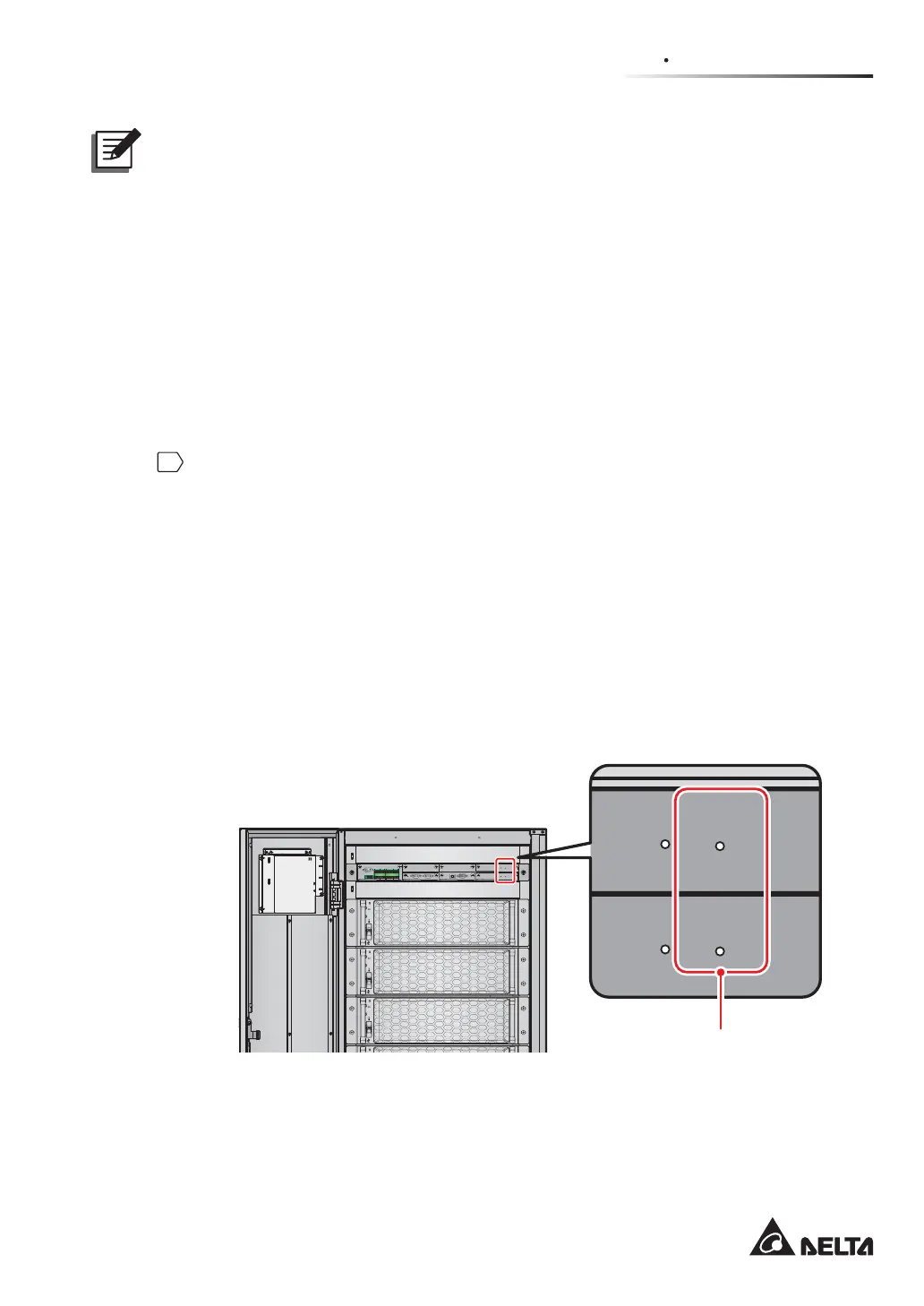
d. Turn on the external battery cabinet’s breaker (Q5), open the front door of the
UPS, and press any of the battery start buttons (Figure 7-2) for 1 second and
release it. After that, the LCD will be on and LCD initial screen (Figure 7-3) will
appear.
DISPLAY
REPO
NC NO
EXT. BATT
TEMP.
BT1 BT2
EXT.SWITCH
STATUS
S1 S2
S3 S4
BT3 BT4
O/P DRY
CONTACT
USB RS-232
P1 P2 P3
P4
P5 P6
I/P DRY
CONTACT
P1 P2
BATT.
START
BATT.
START
P3
P4
PARALLEL
DISPLAY
EMS
/CONSOLE
RESET
GND B A GND B A
MODBUS BMS
(UPS Front View with Door Open)
Battery Start Button x 2
(Figure 7-2: The Position of Battery Start Buttons)
 Loading...