4-11
4
Communication Interfaces
No. Event Description
1 None No set-up.
2 Generator Status Generator status detection.
3 Battery Ground Fail Battery leakage detection.
4
External Battery Breaker
Detection
Status detection of the external battery cabinet’s
breaker or switch.
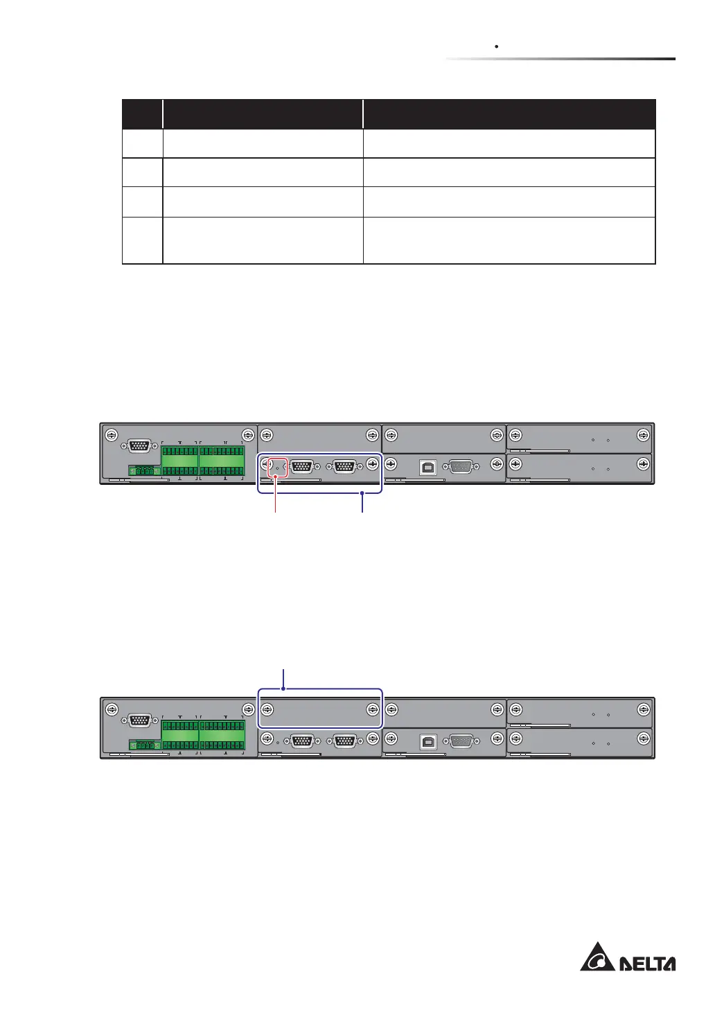
4.1.7 Parallel Communication Card
The UPS has one parallel communication card and the card includes two parallel ports and
one LED indicator. Please see Figure 4-11 for relevant location. If the card work normally,
its LED indicator will illuminate green; if not, the LED indicator will illuminate red. During
LQLWLDOL]DWLRQSURFHVVWKHFDUG¶V/('LQGLFDWRUÀDVKHV\HOORZ
(Figure 4-11: Location of Parallel Communication Card and its LED Indicator)
DISPLAY
REPO
NC NO
EXT. BATT
TEMP.
BT1 BT2
EXT.SWITCH
STATUS
S1 S2
S3 S4
BT3
BT4
O/P DRY
CONTACT
USB RS-232
P1 P2 P3
P4
P5 P6
I/P DRY
CONTACT
P1 P2
BATT.
START
BATT.
START
P3
P4
PARALLEL
Parallel Communication
Card’s LED Indicator
Parallel
Communication Card
You can purchase the optional parallel communication card and install it into the parallel
communication card slot. For the slot location, please refer to Figure 4-12.
(Figure 4-12: Location of Parallel Communication Card Slot)
DISPLAY
REPO
NC NO
EXT. BATT
TEMP.
BT1 BT2
EXT.SWITCH
STATUS
S1 S2
S3 S4
BT3
BT4
O/P DRY
CONTACT
USB RS-232
P1 P2 P3
P4
P5 P6
I/P DRY
CONTACT
P1 P2
BATT.
START
BATT.
START
P3
P4
PARALLEL
Parallel Communication Card Slot
When there are two parallel communication cards installed in the UPS, the lower one is
named the master parallel communication card (the card is a standard accessory) and
the upper one is called the backup parallel communication card (the card is an optional
accessory). Please refer to Figure 4-13 for the two cards and their LED indicators’ location.
 Loading...