5-5
5
Installation and Wiring
y
If you need to move the UPS over a long distance, please use appropriate equipment
like a forklift. Do not use the UPS casters to move the unit over a long distance.
5.4 Fixing the UPS
Please follow the steps below:
1
%HIRUH¿[LQJWKH836LQDGHVLJQDWHGLQVWDOODWLRQDUHDSOHDVHGRXEOHFKHFNZKHWKHU
WKHDUHD¶VÀRRUZHLJKWORDGLQJLVVXႈFLHQWWREHDUWKH836H[WHUQDOEDWWHU\FDELQHWV
DQGKDQGOLQJHTXLSPHQWLHIRUNOLIWWRDYRLGDFFLGHQWV)RU836ÀRRUZHLJKWORDGLQJ
information, please refer to Table 5-1.
2
After the UPS is moved to the designated installation area, use a #17 wrench to
VWDELOL]HWKH836IRXUOHYHOLQJIHHWRQWKHÀRRU3OHDVHQRWHWKDWWKH836PXVWVWDQG
RQWKHÀRRUVWDEO\DQGOHYHOO\ZLWKRXWDQ\WLSSLQJ
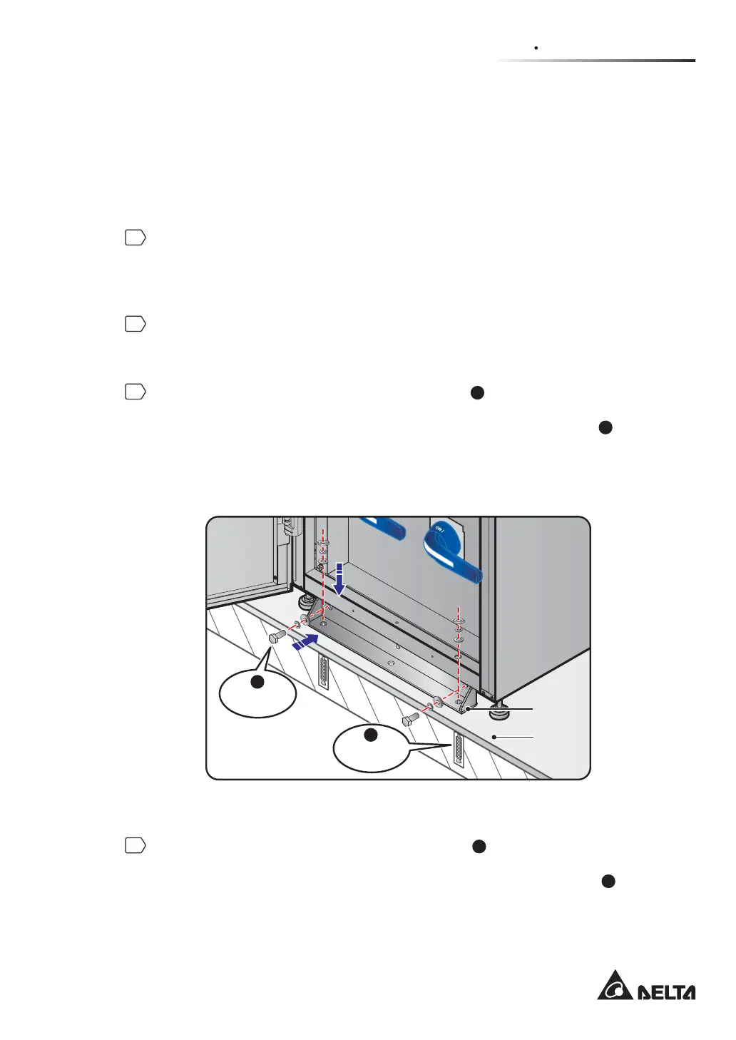
3
Use a 17mm socket wrench and two M10 screws
1
RULJLQDOO\XVHGWR¿[WKHIURQW
balance support on the pallet) to install the front balance support (removed during the
unpacking process) at the front of the UPS. Use the two expansion screws
2
(provided
E\TXDOL¿HGVHUYLFHSHUVRQQHOWR¿[WKHIURQWEDODQFHVXSSRUWRQWKHJURXQGWRDYRLG
UPS movement. Please see Figure 5-3.
BYPASS SWITCH
MANUALBYPASS SWITCH
(Front View)
Ground
Balance
Support
Expansion
Screw x 2
M10 Screw
x 2
1
2
(Figure 5-3: Balance Support Installation_ Front of the UPS)
4
Use a 17mm socket wrench and two M10 screws
1
(originally used to fix the rear
balance support on the pallet) to install the rear balance support (removed during the
unpacking process) at the rear of the UPS. Use the two expansion screws
2
(provided
E\TXDOL¿HGVHUYLFHSHUVRQQHOWR¿[WKHUHDUEDODQFHVXSSRUWRQWKHJURXQGWRDYRLG
UPS movement. Please see Figure 5-4.
 Loading...