3-31
3
Operation Modes
3.2.14
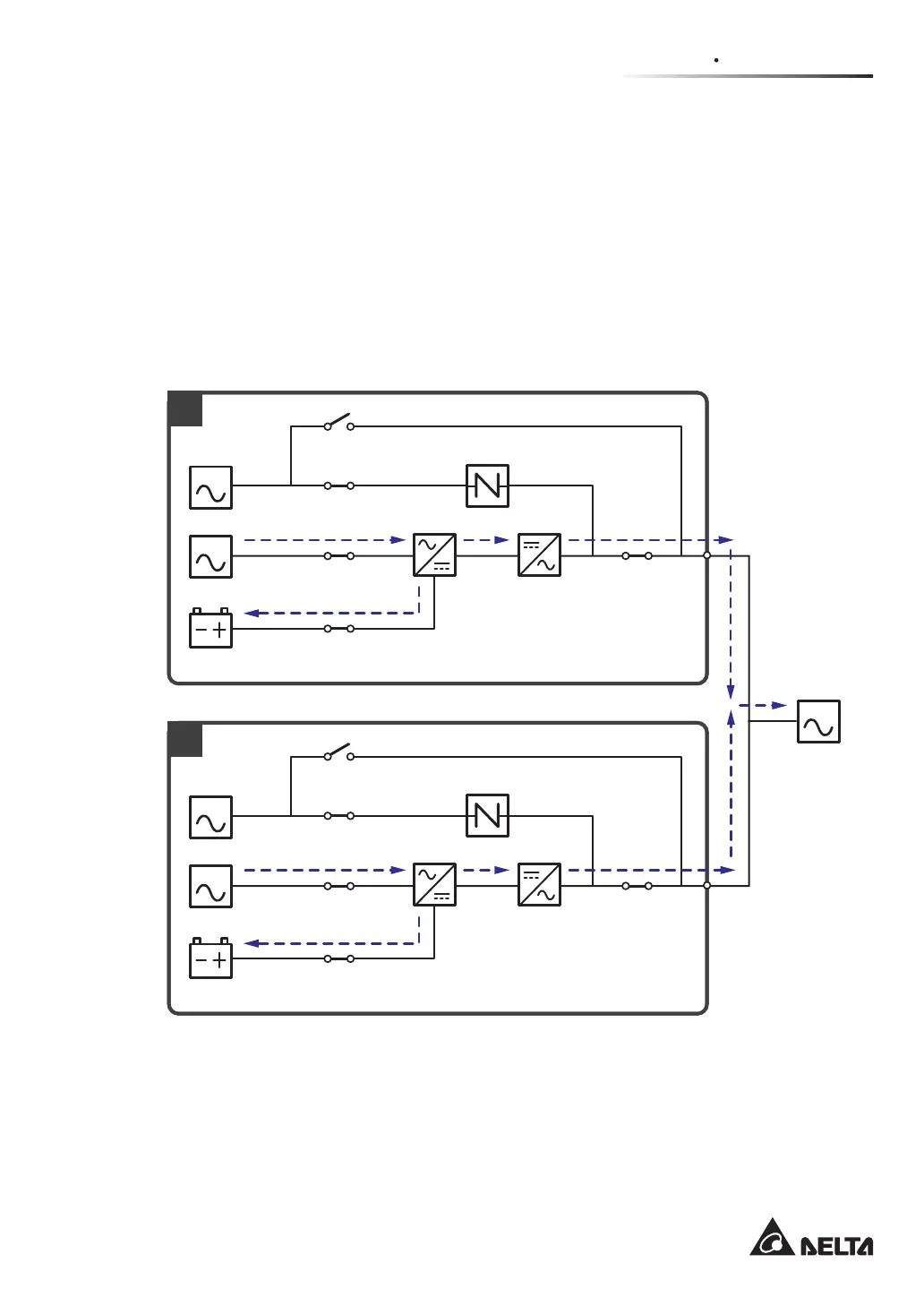
Green Mode_ Dual Input_ Parallel Units
To activate green mode, please refer to 6.2.7 Green Mode Start-up Procedures, 7.6 Main
Screen and 7.10.2 Mode Setting.
)RUSDUDOOHODSSOLFDWLRQJUHHQPRGHLVWKHVDPHDVRQOLQHPRGHEXWWKHGLႇHUHQFHLVWKDW
each system will automatically detect its UPS’s output status (i.e. total load capacity %) to
GHFLGHZKLFKVSHFL¿FSRZHUPRGXOHVVKRXOGEHIXOO\SRZHUHGRQRULGOHLQRUGHUWRDFKLHYH
higher efficiency of the UPS. During green mode, each UPS’s tri-color LED illuminates
green and each UPS’s LCD shows the text ‘Green’ in the upper right corner. Please see
Figure 3-29 for the path of electrical power through the parallel UPSs in green mode.
MAIN
LOAD
MAIN
1
2
BYPA.
BYPA.
Q1
Q2
Q4
Q3
Batteries
Rectifier Inverter
Static Switch
Q1
Q2
Q4
Q3
Batteries
Rectifier Inverter
Static Switch
Q5
Q5
(Figure 3-29: Green Mode Diagram_ Dual Input Parallel Units)
 Loading...