2-5
2
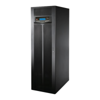
Introduction
y
Both auxiliary power and control circuit adopt redundancy design, which doubly en-
hances UPS reliability.
y
Suitable for top and bottom wiring.
y
Suitable for top and front maintenance for power modules and system components.
y
Generator compatible
y
6XUJHSURWHFWLRQDQG(0,¿OWHUIXQFWLRQV
y
5HPRWHHPHUJHQF\SRZHURႇ
y
Single input and dual input functions.
y
Supports external switch/ breaker status detection.
y
Wide AC input voltage range (full load: 176~276/ 305~477 Vac; <70% load: 132~176/
228~305 Vac) reduces frequent transfer from normal mode to battery mode to save bat-
tery consumption and prolong battery life.
y
Cold-start function when there is no AC power.
y
AC start-up function when the UPS is not connected to the batteries.
WARNING:
Please note that when the UPS is not connected to the batteries, it will not
protect your equipment if the utility power is lost.
y
Connects at maximum four external battery cabinets to extend backup time.
y
Schedulable battery test and battery replacement alarm.
y
Battery temperature monitoring and compensation.
y
Battery monitoring system allows measurement of per battery cell’s voltage and current.
y
Smart battery charger design allows auto-charging or manual charging to shorten
charging time.
y
Provides communication interfaces and a smart slot (where you can install the optional
Relay I/O card for dry contact expansion). Please refer to 4. Communication Interfaces.
y
Provides a parallel communication card slot (where you can install the optional parallel
communication card to increase two redundant parallel ports for parallel communica-
tion). Please refer to 4.1.7 Parallel Communication Card for more information.
y
Built-in RS-232 port and USB port located on the communication interfaces allow moni-
toring and management of the UPS. For relevant location and information, please refer
to Figure 4-3 and Page 4-14.
 Loading...