7-15
7
LCD Display & Settings
7
Frequency
Conversion
MEASUREMENT MAINTENANCE EVENT LOGLOG IN
AdministratorPower Flow
UPS-1.1 SETUP
POWER FLOW
Maintenance
Bypass
Bypass
Mains
90 %
5 mins
Load
30 %
Power Flow
Summary
System Status
09:30
May 10,2018
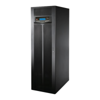
The screen above indicates that the UPS is in frequency conversion mode and the bypass
output is restricted. For frequency conversion mode settings, please refer to 7.10.2 Mode
Setting and 6.2.6 Frequency Conversion Mode Start-up Procedures.
8
Bypass
MEASUREMENT
Power Flow
UPS-1.1 SETUP MAINTENANCE
2
WARNINGLOG IN
Administrator
POWER FLOW
Maintenance
Bypass
Bypass
Mains
90 %
5 mins
Load
30 %
Power Flow
Summary
System Status
09:30
May 10,2018
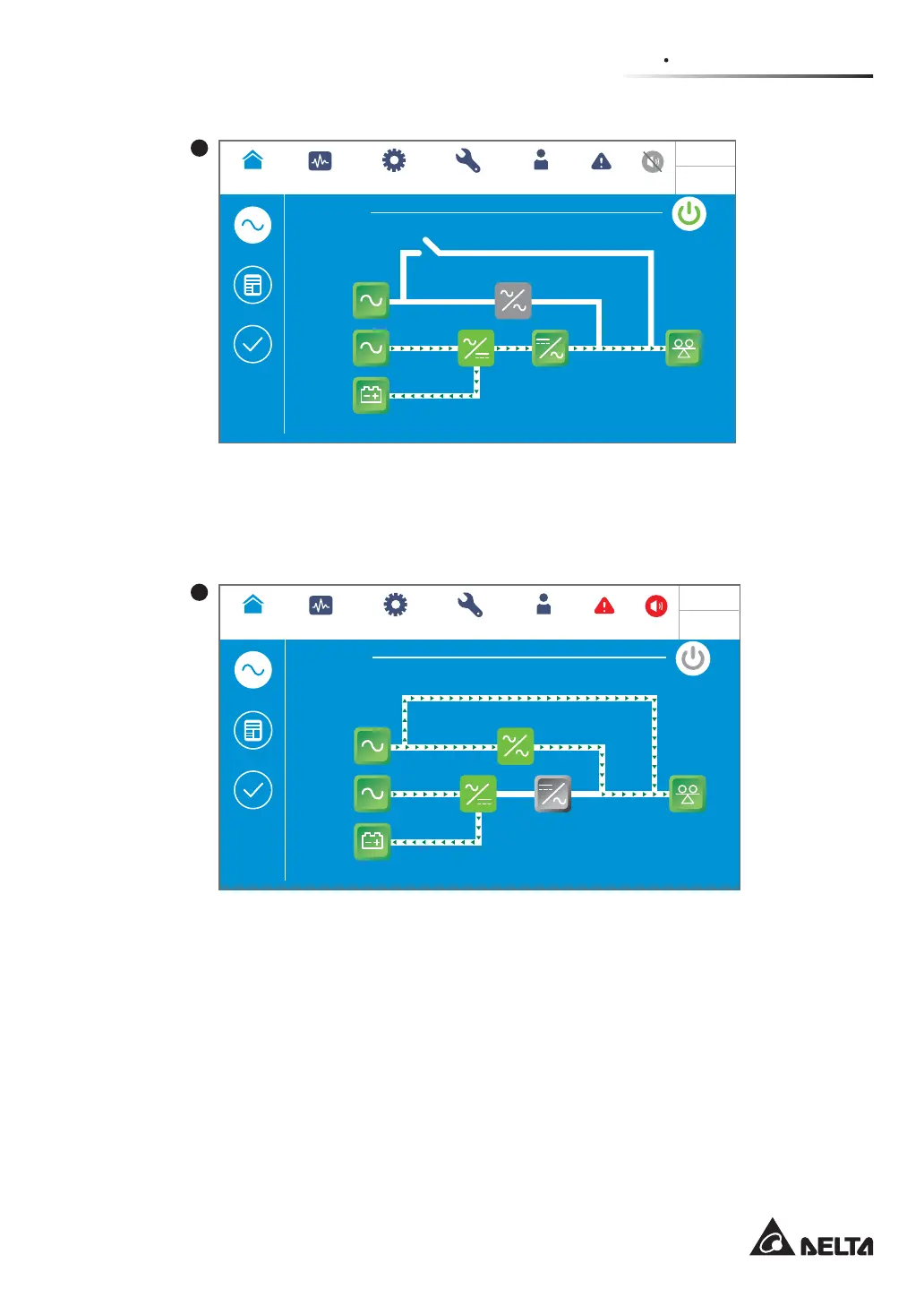
After the Manual Bypass Switch (Q3) is turned on, the UPS will be switched to manual
bypass mode, and the screen above will appear. Before maintenance personnel perform
maintenance, the UPS must be switched to this mode and it must be ensured that all input
SRZHUDQGEDWWHU\SRZHUDUHGLVFRQQHFWHG$IWHUSRZHUGLVFRQQHFWLRQWKH/&'ZLOOEHRႇ
If there is any sudden malfunction in the bypass, the loads will lose power and become
unprotected. Please refer to 6.2.4 Manual Bypass Mode Start-up Procedures.
 Loading...