2-9
2
Introduction
INPUT SWITCH OUTPUT SWITCH
BYPASS SWITCH MANUAL BYPASS SWITCH
DISPLAY
REPO
NC NO
EXT. BATT
TEMP.
BT1 BT2
EXT.SWITCH
STATUS
S1 S2
S3 S4
BT3 BT4
O/P DRY
CONTACT
USB RS-232
P1 P2 P3
P4
P5 P6
I/P DRY
CONTACT
P1 P2
BATT.
START
BATT.
START
P3
P4
PARALLEL
DISPLAY
EMS
/CONSOLE
R
E
S
E
T
GND B A GND B A
MODBUS BMS
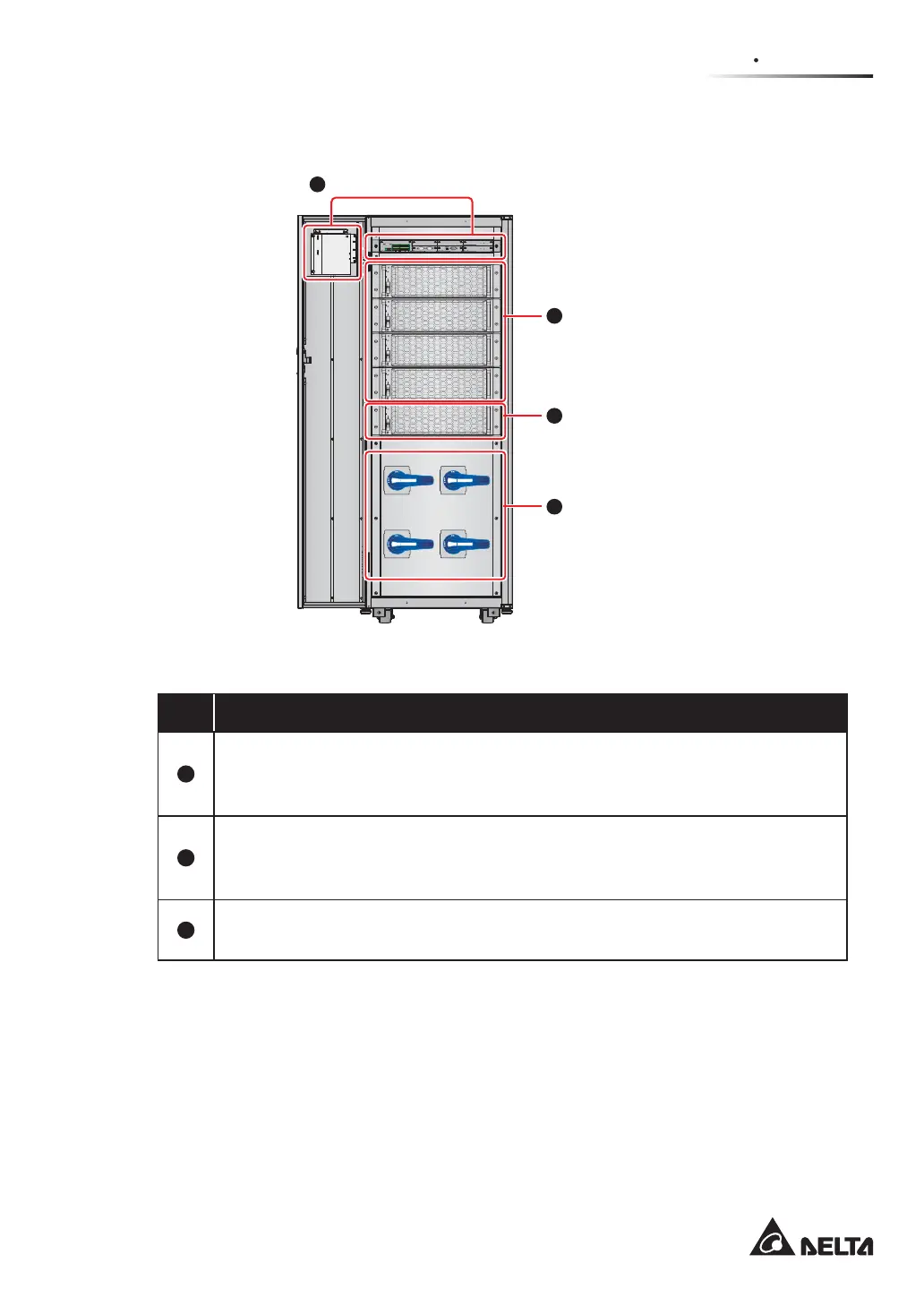
Internal View
(Front View with Door Open)
Communication Interfaces
STS Module
Power Modules
(160kVA: 3 Power Modules)
(200kVA: 4 Power Modules)
1
2
3
4
Input Switch (Q1)
Bypass Switch (Q2)
Manual Bypass Switch (Q3)
Output Switch (Q4)
(Figure 2-4: UPS Internal View (Front View with Door Open)
No. Description
1
The communication interfaces are located at two areas, (1) on the front of the
UPS with front door open and (2) at the rear of the touch panel. For relevant
information, please refer to 4. Communication Interfaces.
2
There are 3 power modules and 4 power modules for 160kVA UPS and 200kVA
UPS respectively. For information about the power module, please refer to 5.8
Power Module.
3
There is one STS module. For the STS module information, please refer to 5.7
STS Module.
 Loading...