C|24 Guide20
Alternate 1/4-inch connectors C|24 input chan-
nels 1, 2, 9, and 10 also have alternate 1/4-inch
balanced TRS connectors on the back panel, la-
beled as follows:
•DI 1
•DI 2
•DI 9
•DI 10
When a source is plugged into a DI input
(1, 2, 9, or 10), the corresponding Mic/Line in-
put (1,2,9,or10) becomes unavailable.
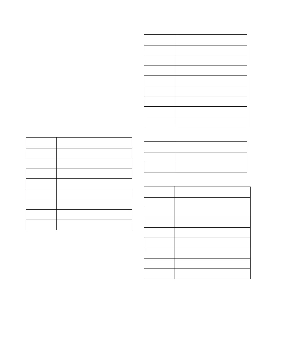
Mic/Line/DI preamplifier inputs are shown in
the following tables.
Mic In 1-8
Channel Signal
1Mic In 1
2Mic In 2
3Mic In 3
4Mic In 4
5Mic In 5
6Mic In 6
7Mic In 7
8Mic In 8
Line In 1-8
Channel Signal
1 Line In 1
2 Line In 2
3 Line In 3
4 Line In 4
5 Line In 5
6 Line In 6
7 Line In 7
8 Line In 8
DI In 1-2 (overrides Mic/Line In 1-2)
Channel Signal
1 Line In 1
2 Line In 2
Mic In 9-16
Channel Signal
1Mic In 9
2Mic In 10
3Mic In 11
4Mic In 12
5Mic In 13
6Mic In 14
7Mic In 15
8Mic In 16