13ECB-VAVS Preloaded Applications
CO
2
Sensor
CO
2
sensor priorities are as follows:
1) Allure EC-Smart-Vue with CO
2
sensor.
2) Allure EC-Smart-Air with CO
2
sensor.
3) CO
2
sensor configured on Input 3.
The Allure EC-Smart-Vue with CO
2
sensor will have priority over the EC-Smart-Air with CO
2
sensor
and over the CO
2
sensor configured on Input 3. For example, if Input 3 is configured for a CO
2
sensor
and there is also one Allure EC-Smart-Vue with CO
2
sensor and one Allure EC-Smart-Air with CO
2
sensor, then the CO
2
Sensor (AV10) variable will only take into account the Allure EC-Smart-Vue with
CO
2
sensor.
CO
2
Control
The CO
2
is calculated by a PID loop. The PID loop is activated if CO2Sensor (AV10) variable is valid
(less or equal to 5000 ppm). In a PID configuration, the default value of the CO2Setpoint (AV52) vari-
able is 1000 ppm.
The PID output is multiplied by 2 in order to control the air flow in the first half of the PID loop (0-50%).
As for the second half of the PID loop (50-100%), the CO2Load (AV53) should be read by the AHU to
adjust the outdoor air damper. You can also use the maximum of all the PID loops to increase the min-
imum fresh air of the AHU supplying this area.
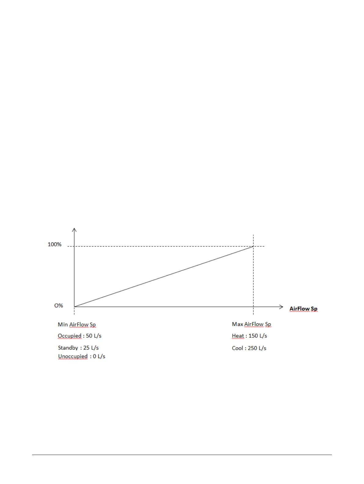
Air Flow Setpoint (AirFlowSP)
The Air Flow calculation depends on the CO
2
load:
Figure2: Air Flow Setpoint Calculation
For example, the AirFlow setpoint is directly linked to the CO2Load (AV53):
£ If CO2Load is 0% then AirFlowSetpoint is equal to MinAirFlow Sp.
£ If CO2Load is 65% then AirFlowSetpoint is equal to the following:
(((MaxFlowSp - MinFlowSp) x 0.65) + MinFlowSp)
The AirFlow setpoint will be the maximum value between the air flow setpoint based on the space
temperature and the CO
2
flow setpoint.
Sequence of Operation