SuperSigma2 AM PMS – V1.5.6 17-1-2020 Page 41 (97) ©2019 DMC GmbH Herten Germany
The following graph shows an example of how these settings work with each other.
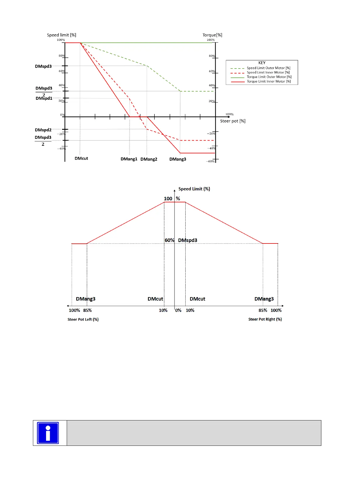
When the setting “M3-14TSingle or Dual Motor ”Si/DL/DR” is set to 3, the speed is limited according to the following
figure:
Speed limiting when “M3-14T Single or Dual Motor ”Si/DL/DR”, is set to 3
In the figure an example is reported for “M1-61T Dual motor cut out ”DMcut”” =10%, “M1-64T Dual motor angle 3
”DMang3”” 85% and “M1-67T Dual motor speed 3 ”DMspd3”” 60%.
• If the steering pot is between ±10%, the speed limit is kept to 100% and it corresponds to a central dead band.
• If the steering pot. is between 10% and 85% (left or right) the speed limit is reduced gradually to 60%.
• If steering pot is greater than 85% speed limit is kept to 60%.
The speed limit is expressed as percentage of parameter “M4-13 Maximum Motor Frequency”. In fact, if for example
“M4-13 Maximum Motor Frequency” is set to 140Hz and “M1-67T Dual motor speed 3 ”DMspd3”” is set to 60%, the
speed limit with steering pot at 100% (left or right) will be 84 Hz.
! IMPORTANT If any speed limit is active the percentage of speed will refer to that speed limit and not
to the “M4-13 Maximum Motor Frequency “Fmotmax””.