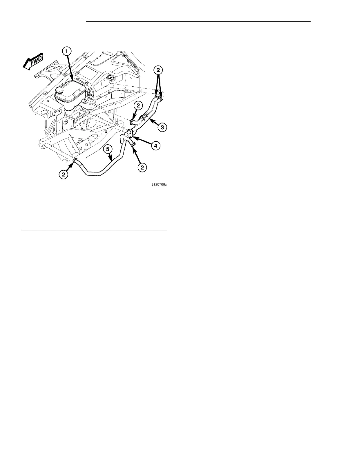
(2) Using spring tension clamp pliers, compress
and slide each clamp away from the end of the hose
being installed.
CAUTION:
DO NOT apply excessive pressure on heater tubes
or connections when install the heater return hose.
Excessive pressure may damage or deform the
heater tubes or connections, causing an engine
coolant leak.
(3) Install each hose end by carefully twisting the
hose back and forth while gently pushing it onto the
tube.
(4) Using spring tension clamp pliers, compress
and slide the clamps onto each end of the hose being
installed.
(5) Install the heater hoses into the retainer
bracket.
(6) Install the heater hose retainer to the right
inner front fender.
(7) Refill the engine cooling system (Refer to 7 -
COOLING - STANDARD PROCEDURE - COOLING
SYSTEM REFILL).
LIQUID LINE
DESCRIPTION
The liquid line is the refrigerant line that goes
from the A/C condenser to the A/C evaporator. The
liquid line contains the A/C variable orifice valve
(VOV) and includes the high side service port. The
liquid line has no serviceable parts except the rubber
O-ring seals and the service port valve core.
CAUTION: Use only O-ring seals specified for the
vehicle. Failure to use correct O-ring seal will cause
the refrigerant system connection to leak.
The O-ring seals used on the connections are made
from a special type of rubber not affected by R-134a
refrigerant. The O-ring seals must be replaced when-
ever the liquid line is removed and installed.
If the liquid line is found to be leaking or is dam-
aged, it must be replaced.
REMOVAL
WARNING: Refer to the applicable warnings and
cautions for this system before performing the fol-
lowing operation (Refer to 24 - HEATING & AIR
CONDITIONING/PLUMBING - WARNINGS) and (Refer
to 24 - HEATING & AIR CONDITIONING/PLUMBING -
CAUTIONS). Failure to follow the warnings and cau-
tions could result in possible personal injury or
death.
(1) Disconnect and isolate the negative battery
cable.
(2) Recover the refrigerant from the refrigerant
system (Refer to 24 - HEATING & AIR CONDITION-
ING/PLUMBING - STANDARD PROCEDURE -
REFRIGERANT SYSTEM RECOVERY).
(3) Remove the air intake ducts from the front of
the air cleaner assembly (Refer to 9 - ENGINE/AIR
INTAKE SYSTEM - REMOVAL).
(4) Remove the bolt that secures the liquid line
bracket to the right inner front fender (Fig. 18).
(5) Remove the bolt that secures the liquid line to
the A/C condenser (Fig. 19).
(6) Disconnect the liquid line from the A/C con-
denser and remove and discard the O-ring seal.
(7) Install plugs in, or tape over the opened liquid
line fitting and condenser port.
(8) Loosen the nut that secures the liquid line to
the A/C evaporator (Fig. 20).
(9) Disconnect the liquid line from the A/C evapo-
rator and remove and discard the O-ring seal.
(10) Install plugs in, or tape over the opened liquid
line fitting and the evaporator tube.
Fig. 17 Heater Return Hose
1 - RADIATOR COOLANT RESERVOIR
2 - HOSE CLAMP (5)
3 - HEATER INLET HOSE
4 - HEATER HOSE RETAINER
5 - HEATER RETURN HOSE
24 - 52 PLUMBING ZB
HEATER RETURN HOSE (Continued)















 To Next Page