REMOVAL
WARNING: Refer to the applicable warnings and
cautions for this system before performing the fol-
lowing operation (Refer to 24 - HEATING & AIR
CONDITIONING/PLUMBING - WARNINGS) and (Refer
to 24 - HEATING & AIR CONDITIONING/PLUMBING -
CAUTIONS). Failure to follow the warnings and cau-
tions could result in possible personal injury or
death.
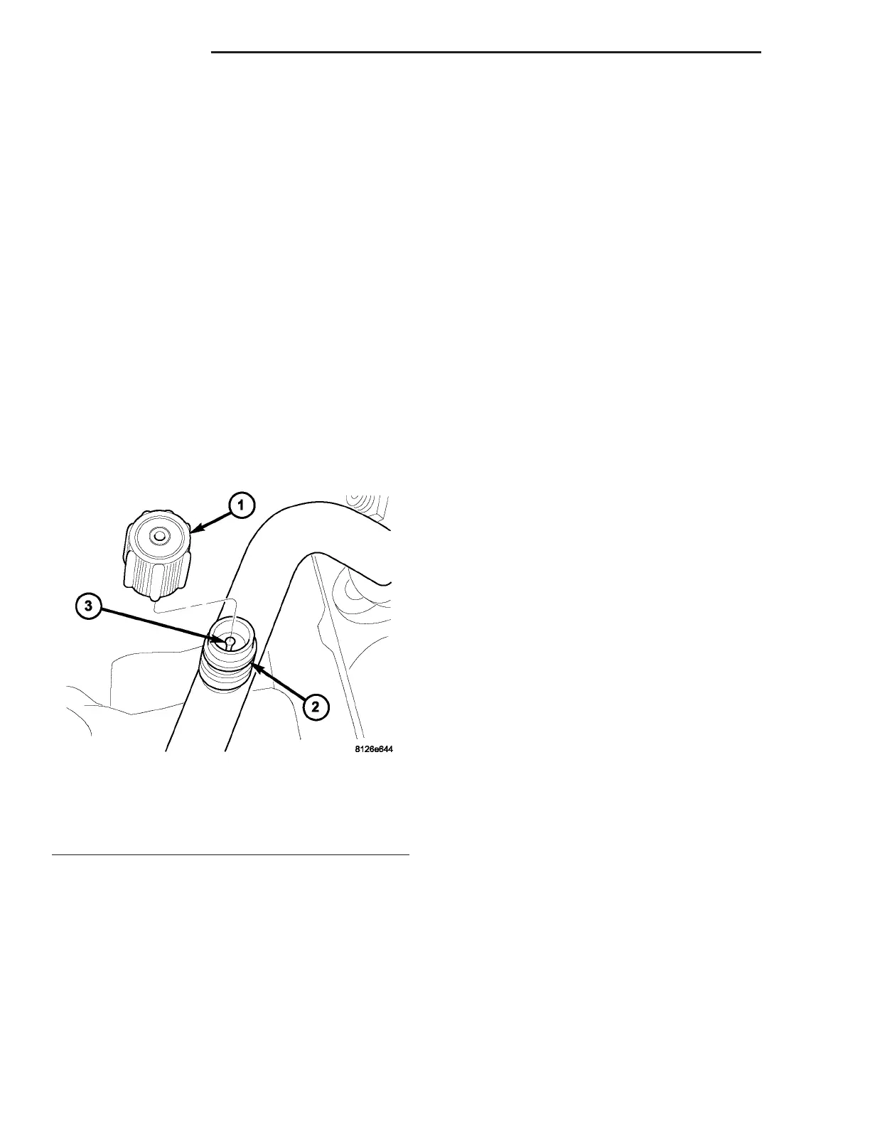
(1) Remove the protective cap from the service port
(Fig. 22).
(2) Recover the refrigerant from the refrigerant
system (Refer to 24 - HEATING & AIR CONDITION-
ING/PLUMBING - STANDARD PROCEDURE -
REFRIGERANT SYSTEM RECOVERY).
(3) Using a Schrader-type valve core tool, remove
the valve core from the service port.
(4) Install a plug in or tape over the opened ser-
vice port(s).
INSTALLATION
(1) Lubricate the valve core with clean refrigerant
oil prior to installation. Use only refrigerant oil of the
type recommended for the A/C compressor in the
vehicle.
(2) Remove the tape or plug from the service port.
CAUTION: A valve core that is not fully seated in
the A/C service port can result in damage to the
valve during refrigerant system evacuation and
charge. Such damage may result in a loss of sys-
tem refrigerant while uncoupling the charge adapt-
ers.
(3) Using a Schrader-type valve core tool, install
and tighten the valve core into the service port(s).
(4) Evacuate the refrigerant system (Refer to 24 -
HEATING & AIR CONDITIONING/PLUMBING -
STANDARD PROCEDURE - REFRIGERANT SYS-
TEM EVACUATE).
(5) Charge the refrigerant system (Refer to 24 -
HEATING & AIR CONDITIONING/PLUMBING -
STANDARD PROCEDURE - REFRIGERANT SYS-
TEM CHARGE).
NOTE: The protective cap helps aid in service port
sealing and helps protects the refrigerant system
from contamination. Remember to always reinstall
the protective cap onto the service port when refrig-
erant system service is complete.
(6) Install the protective cap onto the service port.
SUCTION LINE
DESCRIPTION
The A/C suction line is serviced in two sections.
The front section connects between the accumulator
and the A/C compressor. The rear section connects
between the evaporator and the accumulator and
includes the low side service port. The suction line
has no serviceable parts except the rubber O-ring
seals and the service port valve core.
CAUTION: Use only O-ring seals specified for the
vehicle. Failure to use correct O-ring seal will cause
the refrigerant system connection to leak.
The O-ring seals used on the connections are made
from a special type of rubber not affected by R-134a
refrigerant. The O-ring seals must be replaced when-
ever the suction line is removed and installed.
If the suction line is found to be leaking or is dam-
aged, it must be replaced.
REMOVAL
WARNING: Refer to the applicable warnings and
cautions for this system before performing the fol-
lowing operation (Refer to 24 - HEATING & AIR
CONDITIONING/PLUMBING - WARNINGS) and (Refer
to 24 - HEATING & AIR CONDITIONING/PLUMBING -
CAUTIONS). Failure to follow the warnings and cau-
tions could result in possible personal injury or
death.
Fig. 22 A/C Service Port-Typical
1 - PROTECTIVE CAP
2 - SERVICE PORT
3 - VALVE CORE
24 - 56 PLUMBING ZB
SERVICE PORT VALVE CORE (Continued)















 To Next Page