NOTE: The A/C suction line is serviced in two sec-
tions. The front section connects between the accu-
mulator and the A/C compressor. The rear section
connects between the evaporator and the accumu-
lator and includes the low side service port.
FRONT SECTION
(1) Recover the refrigerant from the refrigerant
system (Refer to 24 - HEATING & AIR CONDITION-
ING/PLUMBING - STANDARD PROCEDURE -
REFRIGERANT SYSTEM RECOVERY).
(2) Disconnect and isolate the negative battery
cable.
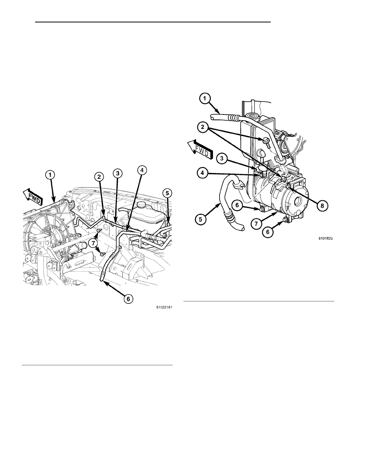
(3) Remove the bolt that secures the suction line
bracket to the right inner front fender (Fig. 23).
(4) Remove the bolt that secures the suction line to
the A/C compressor (Fig. 24).
(5) Disconnect the suction line from the A/C com-
pressor and remove and discard the O-ring seal.
(6) Install plugs in, or tape over the opened suc-
tion line fitting and the compressor port.
(7) Raise and support the vehicle.
(8) Remove the bolts that secure the two suction
line brackets to the front of the engine.
(9) Remove the right front wheel (Refer to 22 -
TIRES/WHEELS - REMOVAL).
(10) Remove the right inner fender splash shield
(Refer to 23 - BODY/EXTERIOR/FRONT WHEEL-
HOUSE SPLASH SHIELD - REMOVAL).
Fig. 23 Suction Line
1 - A/C CONDENSER
2 - HIGH SIDE SERVICE PORT
3 - LIQUID LINE
4 - SUCTION LINE
5 - LOW SIDE SERVICE PORT
6 - TO A/C COMPRESSOR
7 - BOLT
Fig. 24 Suction Line - A/C Compressor
1 - SUCTION LINE
2 - BOLT (2)
3 - A/C COMPRESSOR CLUTCH
4 - UPPER MOUNTING BOLT
5 - A/C DISCHARGE LINE
6 - LOWER MOUNTING BOLT (2)
7 - A/C COMPRESSOR
8 - UPPER MOUNTING BOLT
ZB PLUMBING 24 - 57
SUCTION LINE (Continued)















 To Next Page