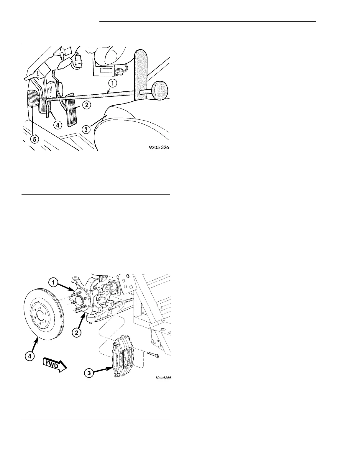
(2) Raise vehicle. (Refer to LUBRICATION &
MAINTENANCE/HOISTING - STANDARD PROCE-
DURE)
(3) Remove wheel and tire assembly. (Refer to 22 -
TIRES/WHEELS - REMOVAL)
(4) Remove brake flex hose banjo bolt. Remove
brake flex hose and seal washers from caliper along
with banjo bolt. Discard washers.
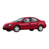
(5) Remove two bolts attaching hydraulic brake
caliper to knuckle (Fig. 31).
(6) Remove hydraulic brake caliper from knuckle.
DISASSEMBLY
Except for piston size, rear calipers are same
design as front calipers. (Refer to 5 - BRAKES/HY-
DRAULIC/MECHANICAL/DISC BRAKE CALIPER -
FRONT - DISASSEMBLY)
ASSEMBLY
Except for piston size, rear calipers are same
design as front calipers. (Refer to 5 - BRAKES/HY-
DRAULIC/MECHANICAL/DISC BRAKE CALIPER -
FRONT - ASSEMBLY)
INSTALLATION
(1) If brake shoes need to be installed in caliper
before installation, (Refer to 5 - BRAKES/HYDRAU-
LIC/MECHANICAL/BRAKE PADS/SHOES -
INSTALLATION)
(2) Install brake caliper on steering knuckle (Fig.
31). Install brake caliper mounting bolts and tighten
to 115 N·m (85 ft. lbs.) torque.
CAUTION: When the brake flex hose is installed on
the caliper, NEW copper seal washers MUST be
used.
(3) Install brake flex hose on brake caliper as fol-
lows:
(a) Place NEW copper seal washers on each side
of banjo fitting located on end of flex hose.
(b) Install banjo bolt through washers and banjo
fitting, into threaded caliper hose port. Only hand
tighten the flex hose to caliper assembly banjo bolt
do not torque. Tighten banjo bolt to 31 N·m (23 ft.
lbs.) torque.
(4) Install wheel and tire assembly (Refer to 22 -
TIRES/WHEELS - INSTALLATION). Progressively
tighten wheel mounting nuts in proper sequence to
122 N·m (90 ft. lbs.) torque.
(5) Lower vehicle.
(6) Remove brake pedal holding tool.
CAUTION: Before moving vehicle, pump brake
pedal several times to ensure vehicle has a firm
brake pedal to adequately stop vehicle.
(7) Bleed brakes as necessary. (Refer to 5 -
BRAKES - STANDARD PROCEDURE)
(8) Road test vehicle making several stops to wear
off any foreign material on brakes and to seat brake
shoes. New brake shoes need to be properly bur-
nished. (Refer to 5 - BRAKES/HYDRAULIC/ME-
CHANICAL/BRAKE PADS/SHOES - STANDARD
PROCEDURE).
Fig. 30 Brake Pedal Holding Tool Installed
1 - BRAKE PEDAL HOLDING TOOL
2 - ACCELERATOR PEDAL
3 - SEAT
4 - BRAKE PEDAL
5 - CLUTCH PEDAL
Fig. 31 Rear Brake Caliper And Rotor Mounting
1 - HUB AND BEARING
2 - KNUCKLE
3 - CALIPER
4 - ROTOR
5 - 22 BRAKES - BASE ZB
DISC BRAKE CALIPER - REAR (Continued)





 To Next Page