CAUTION: When installing piston, force must be
applied to the piston uniformly to avoid cocking
and binding the piston in the bore.
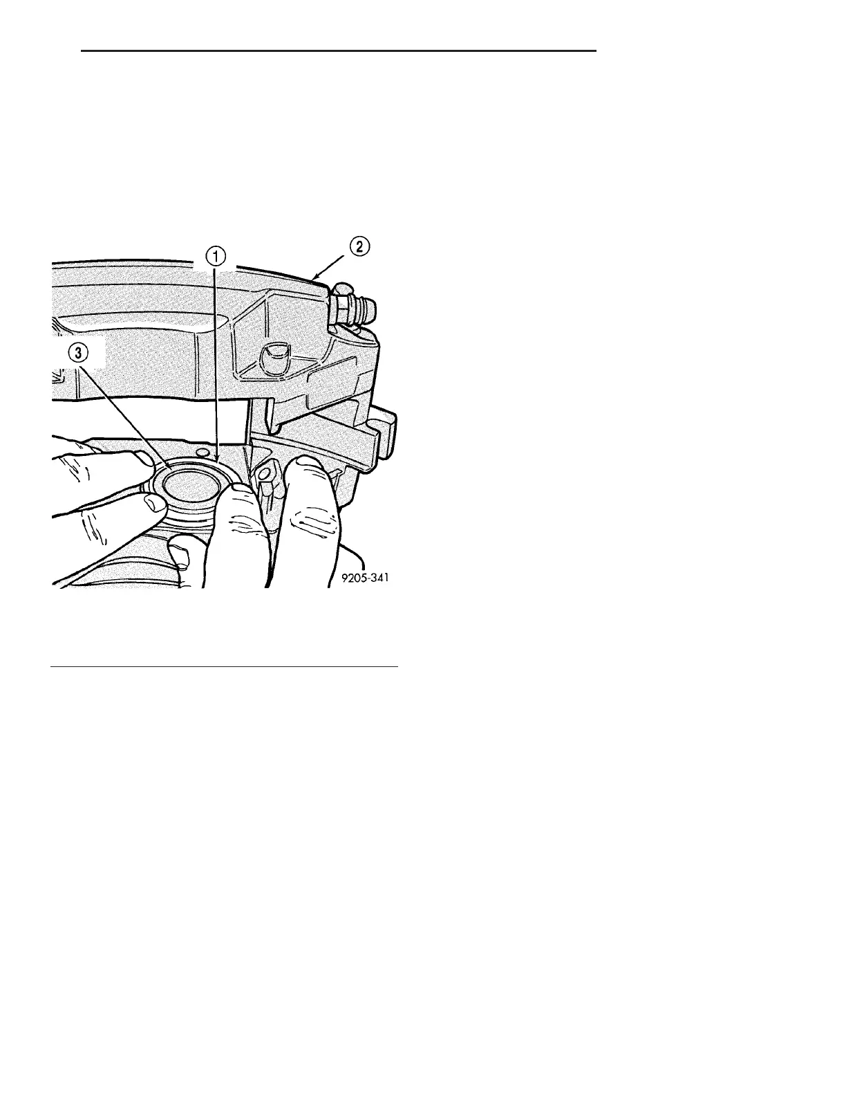
(3) Squarely position piston into top portion of pis-
ton bore. Using finger pressure, evenly apply pres-
sure to top of piston, pressing it into bore until it is
past piston seal, bottomed in bore (Fig. 29).
(4) Using finger pressure, press outer ring of dust
boot into retaining groove surrounding caliper bore
(Fig. 24) until flush with caliper machined surface.
(5) Repeat above procedure for remaining pistons
and bores.
(6) Install bleeder screws in top of caliper.
(7) Install transfer brake fluid tube between
inboard and outboard caliper halves. Tighten tube
nuts to 17 N·m (145 in. lbs.) torque.
(8) Install brake shoes in caliper. (Refer to 5 -
BRAKES/HYDRAULIC/MECHANICAL/BRAKE
PADS/SHOES - INSTALLATION)
(9) Install caliper on vehicle. (Refer to 5 -
BRAKES/HYDRAULIC/MECHANICAL/DISC
BRAKE CALIPER - INSTALLATION)
INSTALLATION
(1) If brake shoes need to be installed in caliper
before installation, (Refer to 5 - BRAKES/HYDRAU-
LIC/MECHANICAL/BRAKE PADS/SHOES -
INSTALLATION)
(2) Install brake caliper on steering knuckle (Fig.
19). Install brake caliper mounting bolts and tighten
to 115 N·m (85 ft. lbs.) torque.
(3) Install brake flex hose on brake caliper as fol-
lows:
(a) Place NEW copper seal washers on each side
of banjo fitting located on end of flex hose.
(b) Install banjo bolt through washers and banjo
fitting, into threaded caliper hose port. Only hand
tighten the flex hose to caliper assembly banjo bolt
do not torque. Tighten banjo bolt to 31 N·m (23 ft.
lbs.) torque.
(4) Install wheel and tire assembly (Refer to 22 -
TIRES/WHEELS - INSTALLATION). Progressively
tighten wheel mounting nuts in proper sequence to
122 N·m (90 ft. lbs.) torque.
(5) Lower vehicle.
(6) Remove brake pedal holding tool.
CAUTION: Before moving vehicle, pump brake
pedal several times to ensure vehicle has a firm
brake pedal to adequately stop vehicle.
(7) Bleed brakes as necessary. (Refer to 5 -
BRAKES - STANDARD PROCEDURE)
(8) Road test vehicle making several stops to wear
off any foreign material on brakes and to seat brake
shoes. New brake shoes need to be properly bur-
nished. (Refer to 5 - BRAKES/HYDRAULIC/ME-
CHANICAL/BRAKE PADS/SHOES - STANDARD
PROCEDURE).
DISC BRAKE CALIPER - REAR
REMOVAL
NOTE: Review all Warnings and Cautions. (Refer to
5 - BRAKES - WARNING)
CAUTION: If more than one caliper will be off the
vehicle at the same time, it is important that each
caliper be marked or tagged indicating which cor-
ner of the vehicle it belongs on, prior to being
removed. Do not allow calipers to get mixed-up.
Except for piston size, front and rear calipers look
alike.
(1) Using a brake pedal holding tool such as shown
(Fig. 30), depress brake pedal down past first inch of
travel and secure in place. This will isolate master
cylinder reservoir from brake hydraulic system and
will not allow brake hydraulic fluid to drain out of
reservoir when lines are opened.
Fig. 29 Piston Installed In Caliper Bore
1 - DUST BOOT
2 - CALIPER ASSEMBLY
3 - CALIPER PISTON
ZB BRAKES - BASE 5 - 21
DISC BRAKE CALIPER - FRONT (Continued)





 To Next Page