(8) Hold up accelerator pedal and install throttle
cable and cable retainer in upper end of pedal shaft
(Fig. 38).
(9) Using lubriplate, or equivalent, coat contact
surface of brake pedal pin (Fig. 37).
(10) Slide power brake booster input rod onto
brake pedal pin and install NEW retainer clip (Fig.
37). Do not use old clip.
(11) Clip clutch push rod onto clutch pedal pin
(Fig. 36).
(12) Connect wiring connector at pedal motor (Fig.
35).
(13) Install NEW brake lamp switch and adjust.
Do not reuse old switch. (Refer to 8 - ELECTRI-
CAL/LAMPS/LIGHTING - EXTERIOR/BRAKE
LAMP SWITCH - INSTALLATION)
(14) Install steering column and components
removed to access it. (Refer to 19 - STEERING/COL-
UMN - INSTALLATION)
(15) Connect battery negative (-) cable to battery
following special Diagnosis And Testing procedure.
(Refer to 8 - ELECTRICAL/RESTRAINTS - DIAG-
NOSIS AND TESTING)
(16) Check operation of adjustable pedals and com-
ponents they control.
POWER BRAKE BOOSTER
DESCRIPTION
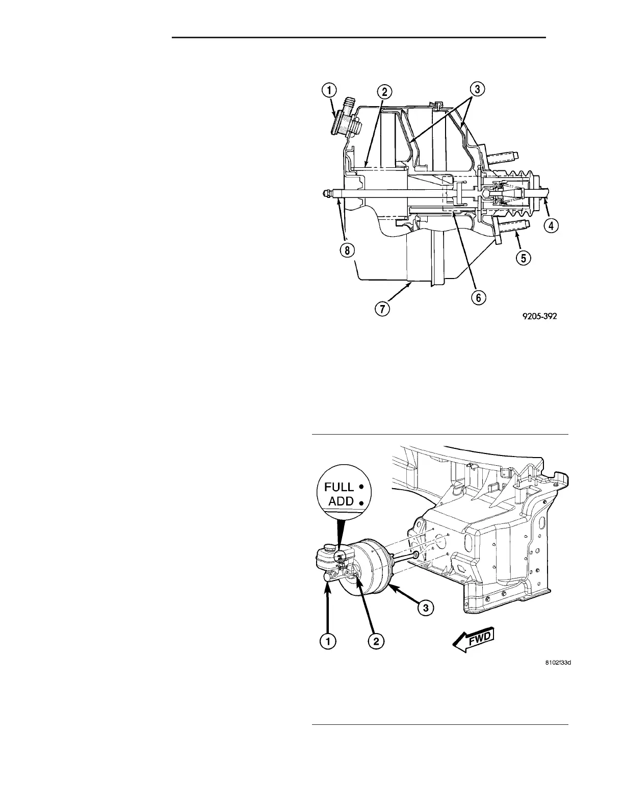
This vehicle uses a 205 mm tandem vacuum oper-
ated power brake booster (Fig. 42).
The power brake booster mounts on the engine
side of the dash panel (Fig. 43). It is externally con-
nected to the brake system by an input push rod to
the brake pedal. A vacuum hose connects the vacuum
check valve on the booster to the intake manifold.
The master cylinder is bolted to the front of the
booster.
The power brake booster can be identified (if
required) by the label attached to the body of the
booster. This label contains the following information:
• Production part number
• Build date
• Manufacturer
NOTE: The power brake booster assembly is not a
repairable part and must be replaced as a complete
unit if it is found to be faulty in any way. The check
valve (Fig. 42) used in the booster is not repairable,
but can be replaced as a separate component of the
power brake booster.
Fig. 42 Typical Power Brake Booster (Cutaway
View)
1 - VACUUM CHECK VALVE
2 - RETURN SPRING
3 - VACUUM DIAPHRAGMS
4 - INPUT ROD
5 - MOUNTING STUDS (4)
6 - VACUUM CONTROL VALVE AREA
7 - POWER BRAKE BOOSTER ASSEMBLY
8 - MASTER CYLINDER PUSH ROD
Fig. 43 Master Cylinder And Booster
1 - MASTER CYLINDER
2 - MASTER CYLINDER MOUNTING NUT
3 - POWER BRAKE BOOSTER
5 - 28 BRAKES - BASE ZB
PEDALS - ADJUSTABLE (Continued)







 To Next Page