(9) Remove four nuts that attach power brake
booster (Fig. 40).
(10) Remove two nuts that attach pedals assembly
to dash (Fig. 40).
(11) Under hood, pull booster/master cylinder for-
ward into engine compartment as far as possible by
hand.
(12) Reposition pedal assembly and remove wiring
components clipped to bracket on left side of pedals
assembly (Fig. 41).
(13) Pull pedals assembly up into column opening
to clear clutch and booster rods, then rotate booster
mounted end of pedals assembly down and out to
remove from under instrument panel.
INSTALLATION
(1) Place pedals assembly under instrument panel
using reverse procedure used for removal.
(2) Attach wiring components to bracket on left
side of pedals assembly (Fig. 41).
(3) Slide pedals assembly into mounted position
and install two nuts that attach pedals assembly to
upper dash (Fig. 40). Do not fully tighten at this
time.
(4) Slide power brake booster mounting studs back
through dash and pedals assembly.
(5) Install four nuts attaching power brake booster
(Fig. 40). Tighten nuts to 28 N·m (21 ft. lbs.) torque.
(6) Tighten two nuts that attach pedals assembly
to upper dash to 28 N·m (21 ft. lbs.) torque.
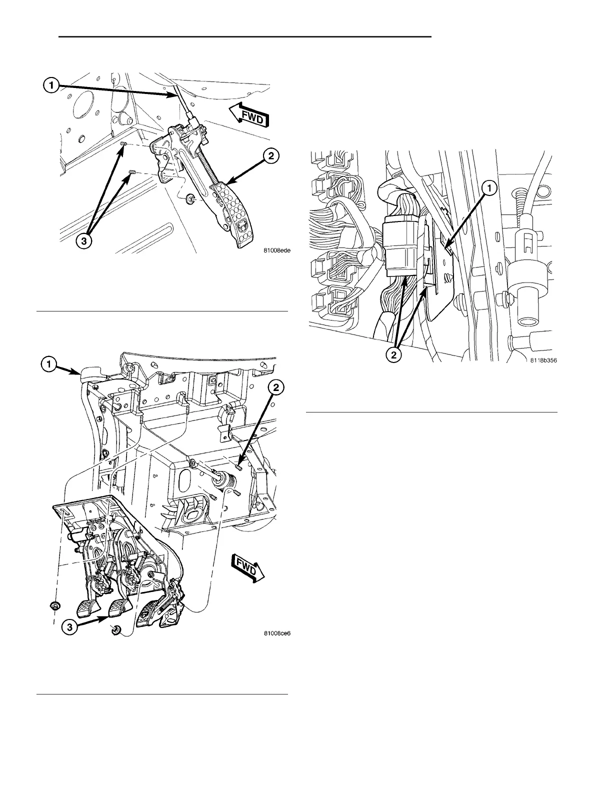
(7) Position accelerator pedal and install nuts
mounting it in place (Fig. 39). Tighten nuts to 12
N·m (105 in. lbs.) torque.
NOTE: When installing throttle cable, make sure it
is routed above steering intermediate shaft before
attaching it to accelerator pedal.
Fig. 39 Accelerator Pedal Mounting
1 - ADJUSTMENT CABLE
2 - ACCELERATOR PEDAL
3 - MOUNTING STUDS
Fig. 40 Adjustable Pedals Mounting
1 - DASH PANEL
2 - BOOSTER STUDS
3 - ADJUSTABLE PEDALS ASSEMBLY
Fig. 41 Wiring Mounted To Bracket
1 - BRACKET
2 - WIRING COMPONENTS
ZB BRAKES - BASE 5 - 27
PEDALS - ADJUSTABLE (Continued)







 To Next Page