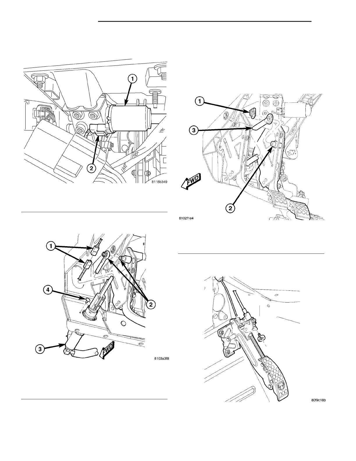
(4) Disconnect wiring connector at pedal motor
(Fig. 35).
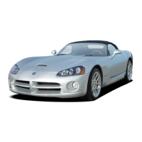
(5) Unclip and remove clutch push rod from clutch
pedal pin (Fig. 36).
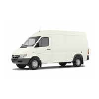
(6) Disconnect brake booster input rod from brake
pedal as follows:
(a) Position a small screwdriver under center
tang on booster input rod retaining clip (Fig. 45)
(b) Lift center tang high enough to clear end of
pedal pin, then slide clip off pedal pin and discard.
Do not reuse clip.
(c) Slide booster input rod off brake pedal pin
(Fig. 37).
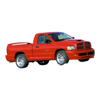
(7) Hold accelerator pedal up and remove cable
retainer and throttle cable from pedal (Fig. 38).
(8) Remove nuts that mount accelerator pedal (Fig.
39).
Fig. 35 Pump Motor Wiring Connection
1 - MOTOR
2 - WIRING CONNECTOR
Fig. 36 Clutch Push Rod To Pedal Connection
1 - PEDAL POSITION SENSOR WIRING CONNECTION
2 - CLUTCH PUSH ROD TO PEDAL CONNECTION
3 - CLUTCH MASTER CYLINDER
4 - PUSH PIN
Fig. 37 Booster Input Rod Attachment To Pedal
1 - RETAINING CLIP
2 - BRAKE PEDAL PIN
3 - BOOSTER INPUT ROD
Fig. 38 Throttle Cable At Accelerator Pedal
5 - 26 BRAKES - BASE ZB
PEDALS - ADJUSTABLE (Continued)










 To Next Page