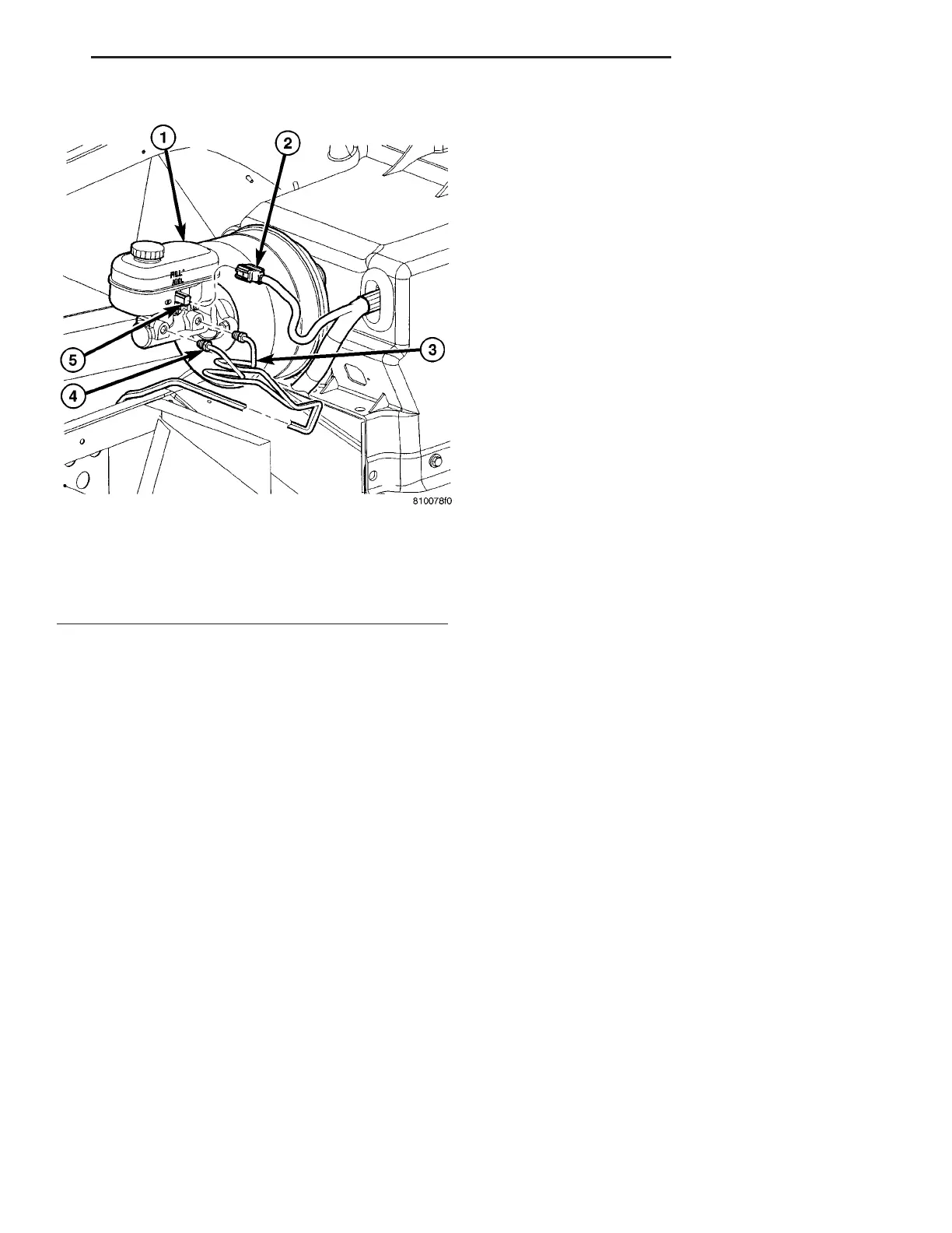
(5) Disconnect primary and secondary brake tubes
from master cylinder housing (Fig. 34). Install plugs
at brake tube outlets.
(6) Remove two nuts attaching master cylinder to
power brake booster.
(7) Slide master cylinder straight out and away
from booster.
INSTALLATION
NOTE: It is not always necessary to bleed the entire
hydraulic system after replacing the master cylin-
der, provided that the master cylinder has been
filled and properly bled prior to installation. The
entire system should only need to be bled if air or
contamination in the system is suspected.
(1) Bleed master cylinder assembly. (Refer to 5 -
BRAKES/HYDRAULIC/MECHANICAL/MASTER
CYLINDER - STANDARD PROCEDURE)
(2) Wipe face of booster clean where master cylin-
der seal comes in contact when installed. Do not get
any cleaner or debris inside booster.
(3) Position master cylinder on mounting studs of
booster. Be sure push rod on booster is correctly
aligned with piston of master cylinder.
(4) Push master cylinder up against front of
booster.
(5) Install master cylinder mounting nuts and
tighten to 28 N·m (250 in. lbs.) torque.
(6) Connect brake tubes to master cylinder pri-
mary and secondary ports (Fig. 34). Tighten fittings
to 17 N·m (145 in. lbs.) torque.
(7) Connect the brake fluid level switch wiring
connector (Fig. 34).
(8) Connect battery negative terminal.
(9) Fill reservoir to proper level with brake fluid.
(10) Road test vehicle to ensure proper operation
of brakes.
PEDALS - ADJUSTABLE
DESCRIPTION
The brake pedal on this vehicle is included in an
assembly known as the adjustable pedals assembly.
The adjustable pedals assembly includes the clutch,
brake and accelerator pedals.
This switch operated assembly is designed to
enable fore and aft repositioning of the clutch, brake
and accelerator pedals. This results in improved
ergonomics in relation to the steering wheel for taller
and shorter drivers. Being able to adjust the pedal
positions also allows the driver to set steering wheel
tilt and seat position to the most comfortable posi-
tion. The effort required for pedal application will not
change regardless of pedal position. All three pedals
adjust at the same time.
The adjustable pedals assembly is serviced as a
complete assembly.
REMOVAL
NOTE: Review all Warnings and Cautions. (Refer to
5 - BRAKES - WARNING)
(1) Disconnect battery negative (-) cable from bat-
tery and isolate.
(2) Access and remove steering column from vehi-
cle. (Refer to 19 - STEERING/COLUMN -
REMOVAL)
(3) Remove brake lamp switch and discard. Do
not reuse switch. (Refer to 8 - ELECTRICAL/
LAMPS/LIGHTING - EXTERIOR/BRAKE LAMP
SWITCH - REMOVAL)
Fig. 34 Master Cylinder
1 - MASTER CYLINDER
2 - WIRING CONNECTOR
3 - PRIMARY BRAKE TUBE
4 - SECONDARY BRAKE TUBE
5 - BRAKE FLUID LEVEL SWITCH
ZB BRAKES - BASE 5 - 25
MASTER CYLINDER (Continued)















 To Next Page