(3) Using lubriplate, or equivalent, coat contact
surface of brake pedal pin.
(4) Slide power brake booster input rod to brake
pedal pin and install a NEW retainer clip (Fig. 46).
Use only a new retainer clip. DO NOT USE OLD
CLIP.
(5) Connect vacuum hoses from intake manifold to
check valve located on booster.
(6) Install master cylinder. (Refer to 5 - BRAKES/
HYDRAULIC/MECHANICAL/MASTER CYLINDER -
INSTALLATION).
(7) Install NEW brake lamp switch and adjust. Do
not reuse old switch. (Refer to 8 - ELECTRICAL/
LAMPS/LIGHTING - EXTERIOR/BRAKE LAMP
SWITCH - INSTALLATION)
(8) Connect battery negative (-) cable to battery.
(9) Bleed brake system as necessary. (Refer to 5 -
BRAKES - STANDARD PROCEDURE)
(10) Check operation of brakes and stop lamps.
ROTOR
DIAGNOSIS AND TESTING - BRAKE ROTOR
Any servicing of the rotor requires extreme care to
maintain the rotor within service tolerances to
ensure proper brake action.
Excessive runout or wobble in a rotor can increase
pedal travel due to piston knock-back. This increases
guide pin sleeve wear due to the tendency of the cal-
iper to follow the rotor wobble.
When diagnosing a brake noise or pulsation, the
machined disc braking surface should be checked and
inspected.
BRAKING SURFACE INSPECTION
Light braking surface scoring and wear is accept-
able. If heavy scoring or warping is evident, the rotor
must be refaced or replaced. (Refer to 5 - BRAKES/
HYDRAULIC/MECHANICAL/ROTORS - STAN-
DARD PROCEDURE).
Excessive wear and scoring of the rotor can cause
improper lining contact on the rotor’s braking sur-
face. If the ridges on the rotor are not removed before
new brake shoes are installed, improper wear of the
shoes will result.
If a vehicle has not been driven for a period of
time, the rotor’s braking surface will rust in the
areas not covered by the brake shoes at that time.
Once the vehicle is driven, noise and chatter from
the disc brakes can result when the brakes are
applied.
Some discoloration or wear of the rotor surface is
normal and does not require resurfacing when lin-
ings are replaced. If cracks or burned spots are evi-
dent, the rotor must be replaced.
ROTOR MINIMUM THICKNESS
Measure rotor thickness at the center of the brake
shoe contact surface. Replace the rotor if it is worn
below minimum thickness or if machining the rotor
will cause its thickness to fall below specifications.
CAUTION: Do not machine the rotor if it will cause
the rotor to fall below minimum thickness.
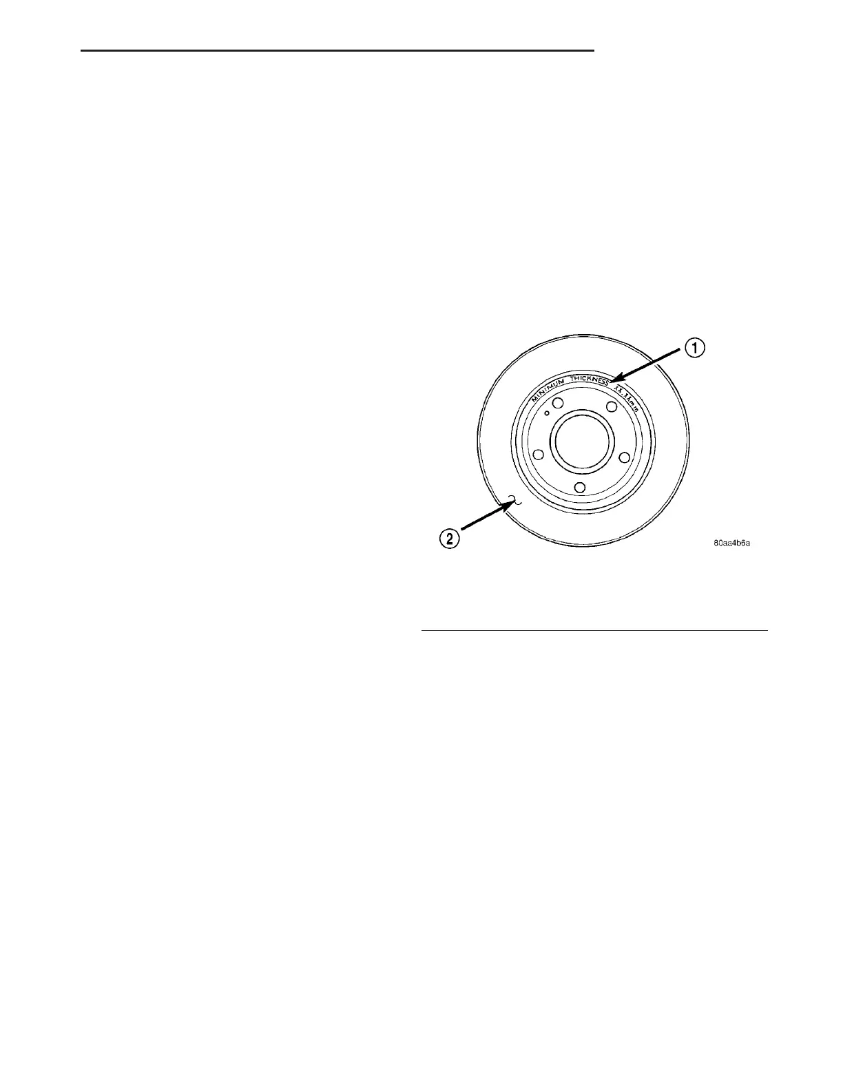
Minimum thickness specifications are cast on the
rotor’s unmachined surface (Fig. 48). Limits can also
be found in this section’s specification table. (Refer to
5 - BRAKES/HYDRAULIC/MECHANICAL/ROTOR -
SPECIFICATIONS)
ROTOR THICKNESS VARIATION
Thickness variation in a rotor’s braking surface
can result in pedal pulsation, chatter and surge. This
can also be caused by excessive runout in the rotor or
the hub.
Rotor thickness variation measurements should be
made in conjunction with measuring runout. Mea-
sure thickness of the brake rotor at 12 equal points
around the rotor braking surface with a micrometer
at a radius approximately 25 mm (1 inch) from edge
of rotor (Fig. 49). If thickness measurements vary
beyond the specification listed in the specification
table (Refer to 5 - BRAKES/HYDRAULIC/MECHAN-
ICAL/ROTOR - SPECIFICATIONS), the rotor should
refaced or replaced. (Refer to 5 - BRAKES/HYDRAU-
LIC/MECHANICAL/ROTOR - STANDARD PROCE-
DURE).
Fig. 48 Minimum Brake Rotor Thickness Markings
(Typical)
1 - ROTOR MINIMUM THICKNESS MARKING
2 - ROTOR
ZB BRAKES - BASE 5 - 31
POWER BRAKE BOOSTER (Continued)





 To Next Page