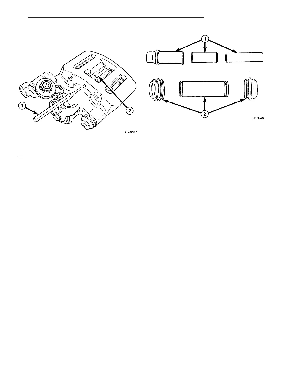
(14) Using a pin punch, tap parking brake shoe
retaining pin out of caliper (Fig. 64).
(15) Remove anti-rattle spring and parking brake
shoes.
DISASSEMBLY
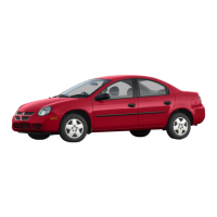
NOTE: The only serviceable parts of the parking
brake caliper are the guide pin bushing compo-
nents (Fig. 65). Use the following procedure to ser-
vice these items.
(1) Remove parking brake caliper from vehicle and
remove parking brake shoes from caliper. (Refer to 5
- BRAKES/PARKING BRAKE/CALIPER -
REMOVAL)
(2) To remove upper guide pin bushing:
(a) Push steel sleeve out pad side of caliper.
(b) Remove plastic sleeve.
(c) Remove rubber bushing from caliper.
(3) To remove lower guide pin bushing:
(a) Push steel sleeve/bushing out of caliper
(b) Remove rubber boots.
ASSEMBLY
(1) Lubricate bushing components with appropri-
ate lubricant (Fig. 65).
(2) To install lower guide pin bushing:
(a) Install rubber boot on one end of bore in cal-
iper.
(b) Insert steel sleeve/bushing into opposite end
of bore in caliper.
(c) Push steel sleeve/bushing past centered posi-
tion in bore of caliper, then install inner lip of boot
into groove on end of sleeve/bushing.
(d) Install remaining boot on opposite end of
bore in caliper.
(e) Slide steel sleeve/bushing back to center in
bore, then install inner lip of remaining boot into
groove on that end of sleeve/bushing.
(3) To install upper guide pin bushing:
(a) Insert rubber bushing into bore from pad
side of caliper.
(b) Insert plastic sleeve into rubber bushing.
(c) Install and center steel sleeve in plastic
sleeve/bushing.
(4) Install brake shoes, then install caliper on
vehicle. (Refer to 5 - BRAKES/PARKING BRAKE/
CALIPER - INSTALLATION)
INSTALLATION
NOTE: Brake shoes must be removed to perform
Step 1.
(1) If parking brake caliper piston is not fully
seated in its bore, seat piston as follows:
(a) Insert double-pin end of Piston Retractor,
Special Tool 6366, into holes in top of piston (Fig.
66).
(b) Rotate Piston Retractor clockwise until pis-
ton is fully seated (bottomed) in its bore. Remove
tool.
(2) Install brake shoes as follows:
(a) Install parking brake shoes in caliper
(Inboard and outboard shoes are identical).
(b) Position anti-rattle spring, then slide retain-
ing pin through anti-rattle spring and holes in
shoes (Fig. 67).
Fig. 64 Shoe Retaining Pin Removal
1 - PIN PUNCH
2 - RETAINING PIN
Fig. 65 Guide Pin Bushing Components
1 - UPPER BUSHING COMPONENTS
2 - LOWER BUSHING COMPONENTS
ZB BRAKES - BASE 5 - 41
CALIPER - PARKING BRAKE (Continued)





 To Next Page