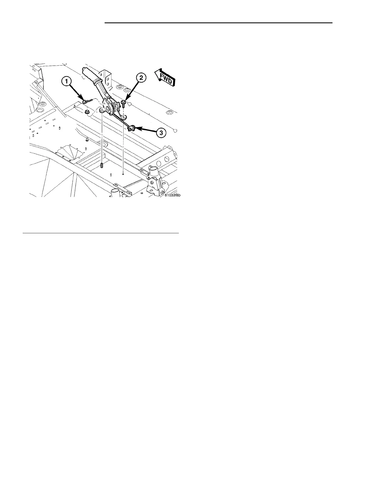
(8) Remove nut and bolt fastening lever in place
(Fig. 71).
(9) Remove parking brake lever.
INSTALLATION
WARNING: THE AUTOMATIC ADJUSTING FEATURE
OF THIS PARKING BRAKE LEVER CONTAINS A
CLOCKSPRING LOADED TO APPROXIMATELY 19
POUNDS. DO NOT RELEASE THE AUTOMATIC
ADJUSTER LOCKOUT DEVICE UNLESS THE PARK-
ING BRAKE CABLES AND EQUALIZER ARE CON-
NECTED TO THE LEVER OUTPUT CABLE. KEEP
HANDS OUT OF AUTOMATIC ADJUSTER SECTOR
AND PAWL AREA. FAILURE TO OBSERVE CAUTION
IN HANDLING THIS MECHANISM COULD LEAD TO
SERIOUS INJURY.
(1) Place lever into position in vehicle and install
nut and bolt fastening lever in place (Fig. 71).
Tighten fasteners to 25 N·m (19 ft. lbs.) torque.
(2) Connect wiring connector at parking brake
indicator switch (Fig. 70).
(3) Install parking brake cables into equalizer on
parking brake lever output cable (Fig. 69).
(4) Ensure that parking brake cables are correctly
installed on equalizer and aligned with cable track
on parking brake lever.
(5) Keeping hands clear of automatic adjuster sec-
tor and pawl area, firmly grasp screwdriver (pin
punch or locking pin if a new lever has been
installed) installed in lever mechanism (Fig. 68), then
quickly remove it from parking brake lever mecha-
nism. This action allows parking brake lever mecha-
nism to automatically take up any slack.
(6) Cycle parking brake lever once to position
parking brake cables, then return lever its released
position.
(7) Raise vehicle far enough for rear wheels to
clear floor. (Refer to LUBRICATION & MAINTE-
NANCE/HOISTING - STANDARD PROCEDURE)
(8) Check rear wheels of vehicle. They should
rotate freely without dragging with lever in released
position.
(9) Fully apply parking brake lever.
(10) Check rear wheels of vehicle. They should not
rotate when lever is in full-applied position.
(11) Lower vehicle.
(12) Install center console. (Refer to 23 - BODY/IN-
TERIOR/CENTER CONSOLE - INSTALLATION)
(13) Remove blocks from tire and wheels assem-
blies.
PADS/SHOES - PARKING
BRAKE
REMOVAL
NOTE: Review all Warnings and Cautions. (Refer to
5 - BRAKES - WARNING)
(1) Raise vehicle. (Refer to LUBRICATION &
MAINTENANCE/HOISTING - STANDARD PROCE-
DURE)
(2) Remove wheel and tire assembly. (Refer to 22 -
TIRES/WHEELS - REMOVAL)
(3) Remove hair pin from brake shoe retaining pin
(Fig. 75).
(4) Using a pin punch, tap parking brake shoe
retaining pin until spring ring on end of retaining
pin is disengaged from caliper housing (Fig. 72).
Leave pin in place to hold shoes and anti-rattle clip
in place on caliper.
(5) Remove two bolts attaching parking brake cal-
iper to knuckle (Fig. 73).
(6) Remove parking brake caliper from knuckle.
Support brake caliper by hanging it from upper con-
trol arm using mechanics wire.
(7) Remove previously loosened parking brake shoe
retaining pin from caliper, removing anti-rattle
spring and parking brake shoes upon doing so.
INSTALLATION
(1) Insert double-pin end of Piston Retractor, Spe-
cial Tool 6366, into holes in top of piston (Fig. 74).
(2) Rotate Piston Retractor clockwise until piston
is fully seated (bottomed) in its bore. Remove tool.
Fig. 71 Parking Brake Lever
1 - LOCKING PIN (USED TO LOCK OUT AUTO-ADJUSTER)
2 - PARKING BRAKE LEVER
3 - EQUALIZER
5 - 44 BRAKES - BASE ZB
LEVER - PARKING BRAKE (Continued)












 To Next Page