(1) Make sure all hydraulic fluid lines are installed
and properly torqued.
(2) Connect the DRBIIIt scan tool to the Data
Link Connector. The connector is located under the
lower instrument panel to the left of the clutch pedal.
(3) Using the DRBIIIt, check to make sure the
CAB does not have any fault codes stored. If it does,
clear them using the DRBIIIt.
WARNING: WHEN BLEEDING THE BRAKE SYSTEM
WEAR SAFETY GLASSES. A CLEAR BLEED TUBE
MUST BE ATTACHED TO THE BLEEDER SCREWS
AND SUBMERGED IN A CLEAR CONTAINER FILLED
PART WAY WITH CLEAN BRAKE FLUID. DIRECT
THE FLOW OF BRAKE FLUID AWAY FROM YOUR-
SELF AND THE PAINTED SURFACES OF THE VEHI-
CLE. BRAKE FLUID AT HIGH PRESSURE MAY
COME OUT OF THE BLEEDER SCREWS WHEN
OPENED.
(4) Bleed the base brake system using the stan-
dard pressure or manual bleeding procedure. (Refer
to 5 - BRAKES - BASE - STANDARD PROCEDURE)
(5) Using the DRBIIIt, select ANTILOCK
BRAKES, followed by MISCELLANEOUS, then
BLEED BRAKES. Follow the instructions displayed.
When the scan tool displays TEST COMPLETED,
disconnect the scan tool and proceed.
(6) Bleed the base brake system a second time.
Check brake fluid level in the reservoir periodically
to prevent emptying, causing air to enter the hydrau-
lic system.
(7) Fill the master cylinder reservoir to the full
level.
(8) Test drive the vehicle to be sure the brakes are
operating correctly and that the brake pedal does not
feel spongy.
SPECIFICATIONS
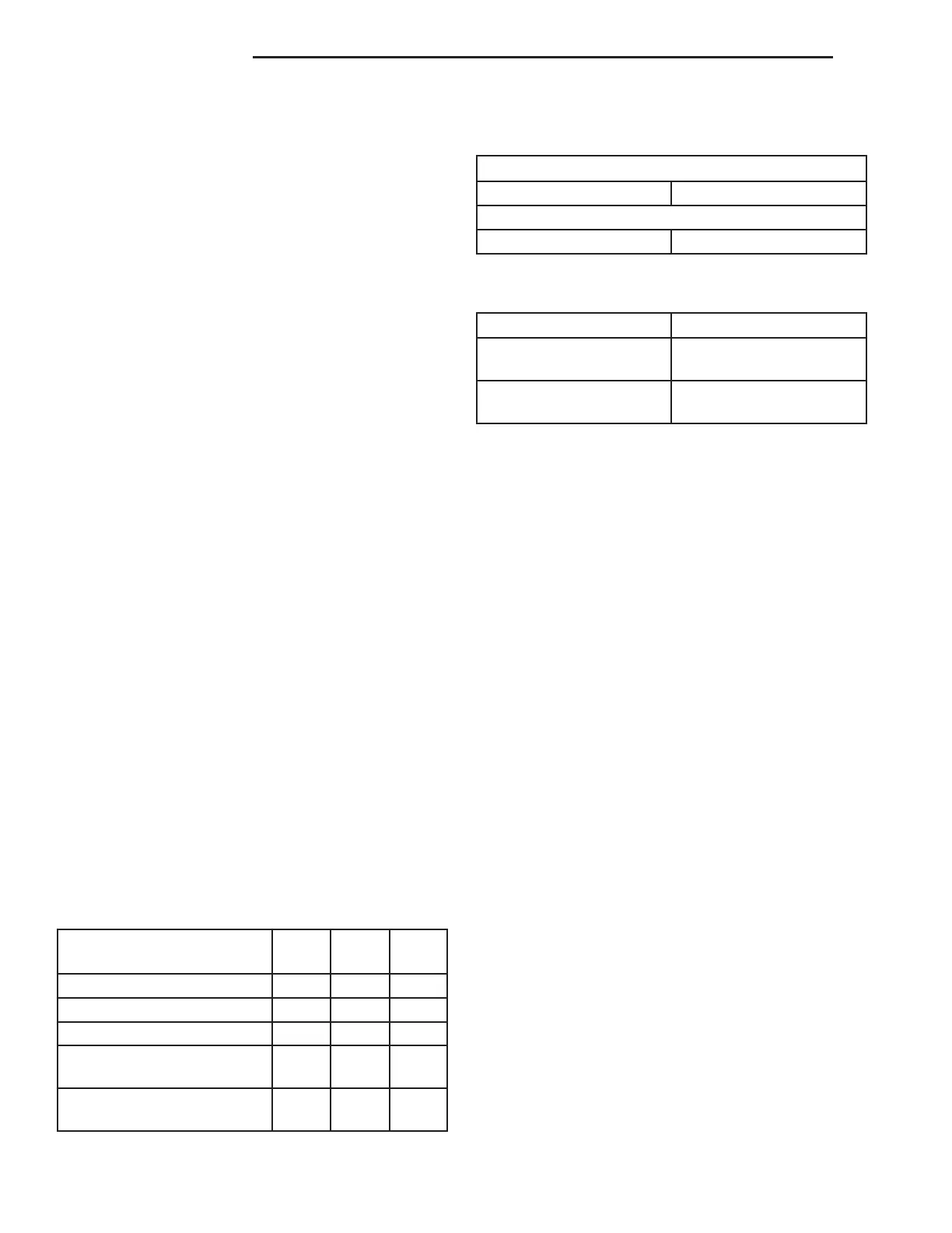
ANTILOCK BRAKE SYSTEM FASTENER
TORQUE
DESCRIPTION N·m
Ft.
Lbs.
In.
Lbs.
Brake Tube Nuts 17 12 145
CAB Mounting Bolts 2 — 17
ICU Mounting Bolts 10 — 85
Tone Wheel (Front) Mount-
ing Bolt
17 13 150
Wheel Speed Sensor Head
Mounting Bolt
11 — 100
TONE WHEEL RUNOUT
FRONT TONE WHEEL:
Maximum Runout 0.37 mm (0.015 in.)
REAR TONE WHEEL:
Maximum Runout 0.37 mm (0.015 in.)
WHEEL SPEED SENSOR AIR GAP
DESCRIPTION SPECIFICATION
FRONT SENSOR
0.127 – 1.20 mm
0.005 – 0.047 in.
REAR SENSOR
0.127 – 1.20 mm
0.005 – 0.047 in.
TONE WHEEL
REMOVAL - FRONT TONE WHEEL
NOTE: Review all Warnings and Cautions. (Refer to
5 - BRAKES - WARNING)
(1) Raise vehicle. (Refer to LUBRICATION &
MAINTENANCE/HOISTING - STANDARD PROCE-
DURE)
(2) Remove wheel and tire assembly. (Refer to 22 -
TIRES/WHEELS - REMOVAL)
(3) Remove brake caliper from knuckle and brake
rotor and hang out of the way. (Refer to 5 - BRAKES/
HYDRAULIC/MECHANICAL/BRAKE PADS/SHOES
- REMOVAL)
(4) Using hex wrench or driver socket, remove
screw retaining tone wheel to hub and bearing (Fig.
1).
(5) Remove tone wheel.
INSPECTION - TONE WHEEL
Tone wheels can cause erratic wheel speed sensor
signals. Inspect tone wheels for the following possible
causes.
• missing, chipped, or broken teeth
• contact with the wheel speed sensor
• wheel speed sensor to tone wheel alignment
• wheel speed sensor to tone wheel clearance
• excessive tone wheel runout
• tone wheel loose on its mounting surface
Rear tone wheels are pressed onto their mounting
surfaces and should not rotate independently from
the mounting surface.
If a front tone wheel is found to need replacement,
the tone wheel can be replaced as a separate compo-
nent. (Refer to 5 - BRAKES/ELECTRICAL/TONE
WHEEL - REMOVAL)
5 - 50 BRAKES - ABS ZB
BRAKES - ABS (Continued)





 To Next Page