If a rear tone wheel is found to need replacement,
the axle shaft must be serviced. No attempt should
be made to replace just the tone wheel. (Refer to 3 -
DIFFERENTIAL & DRIVELINE/HALF SHAFT/
AXLE SHAFT - REMOVAL)
Check the gap between the speed sensor head and
the tone wheel to ensure it is within specifications.
(Refer to 5 - BRAKES - ABS - SPECIFICATIONS)
Excessive wheel speed sensor runout can cause
erratic wheel speed sensor signals. For the maximum
allowed tone wheel runout specification, (Refer to 5 -
BRAKES - ABS - SPECIFICATIONS). If front tone
wheel runout is excessive, determine if it is caused
by a defect in the tone wheel or hub and bearing. If
rear tone wheel runout is excessive, determine if it is
caused by a defect in the axle shaft assembly or hub
and bearing. Replace as necessary.
INSTALLATION - FRONT TONE WHEEL
(1) Make sure mating surface of tone wheel and
hub and bearing is clean.
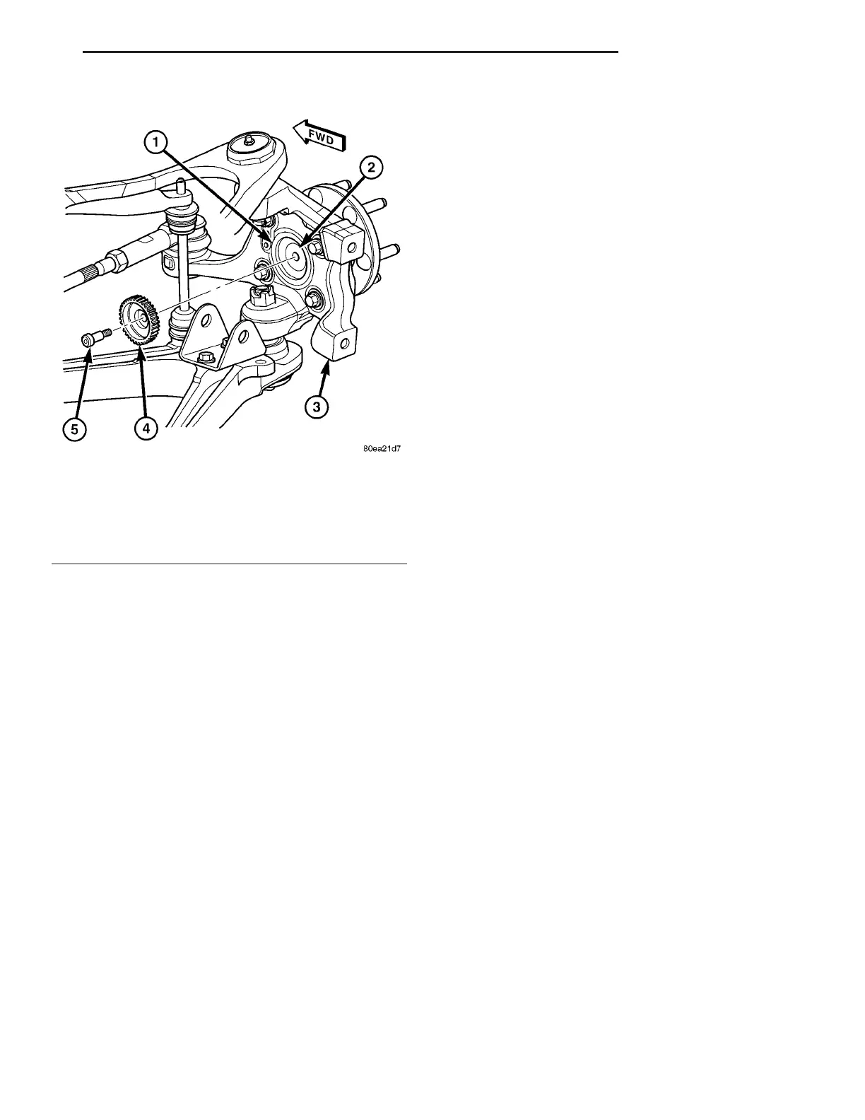
(2) Install tone wheel through the seal on rear of
knuckle and against rear of hub and bearing assem-
bly (Fig. 1).
(3) Using same bolt or identical replacement bolt,
mount tone wheel to hub and bearing. Tighten bolt to
17 N·m (150 in. lbs.) torque.
(4) Verify proper wheel speed sensor-to-tone wheel
air gap. (Refer to 5 - BRAKES - ABS - SPECIFICA-
TIONS)
(5) Install brake caliper. (Refer to 5 - BRAKES/HY-
DRAULIC/MECHANICAL/BRAKE PADS/SHOES -
INSTALLATION)
(6) Install tire and wheel assembly (Refer to 22 -
TIRES/WHEELS - INSTALLATION). Progressively
tighten the wheel mounting nuts in the proper
sequence to 122 N·m (90 ft. lbs.) torque.
(7) Lower vehicle.
(8) Road test vehicle to ensure proper operation of
base and antilock brakes.
WHEEL SPEED SENSOR -
FRONT
REMOVAL
NOTE: Before proceeding review Warnings and
Cautions. (Refer to 5 - BRAKES - WARNING) (Refer
to 5 - BRAKES - CAUTION).
(1) Raise vehicle. (Refer to LUBRICATION &
MAINTENANCE/HOISTING - STANDARD PROCE-
DURE).
(2) Remove wheel and tire assembly. (Refer to 22 -
TIRES/WHEELS - REMOVAL)
(3) Disconnect vehicle wiring harness from wheel
speed sensor wiring connector at frame rail.
(4) Remove sensor wiring connector clip from
frame rail.
(5) Remove sensor harness from routing clips
along brake flex hose.
(6) Remove bolt fastening sensor head to steering
knuckle (Fig. 2).
CAUTION: When removing a wheel speed sensor
from the knuckle, do not use pliers on the sensor
head. This may damage the sensor head. If the sen-
sor has seized, use a hammer and a punch to tap
the edge of the sensor head ear, rocking the sensor
side-to-side until free.
(7) Carefully remove sensor head from steering
knuckle.
INSTALLATION
CAUTION: Failure to install wheel speed sensors
properly may result in contact with moving parts or
an over extension of wires causing an open circuit.
Be sure that sensor harnesses are installed, routed,
and clipped properly.
Fig. 1 Tone Wheel Mounting
1 - SEAL
2 - HUB AND BEARING
3 - KNUCKLE
4 - TONE WHEEL
5 - MOUNTING BOLT
ZB BRAKES - ABS 5 - 51
TONE WHEEL (Continued)










 To Next Page