ABS HYDRAULIC CIRCUIT AND SOLENOID VALVE
FUNCTION
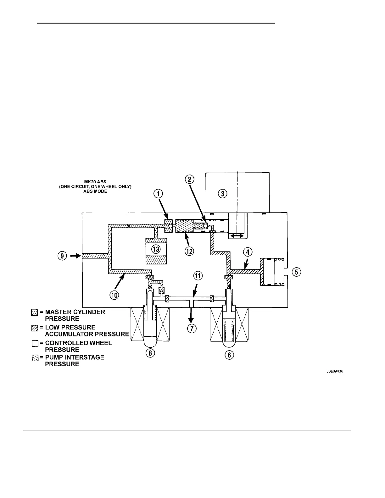
The hydraulic diagram (Fig. 5) shows the vehicle in
the ABS braking mode. The diagram shows one
wheel is slipping because the driver is attempting to
stop the vehicle at a faster rate than is allowed by
the surface on which the tires are riding.
• The normally open and normally closed valves
modulate (build/decay) the brake hydraulic pressure
as required.
• The pump/motor is switched on so that the
brake fluid from the low pressure accumulators is
returned to the master cylinder circuits.
• The brake fluid is routed to either the master
cylinder or the wheel brake depending on the posi-
tion of the normally open valve.
Fig. 5 ABS Mode Hydraulic Circuit
1 - OUTLET VALVE 8 - NORMALLY OPEN VALVE (MODULATING)
2 - PUMP PISTON 9 - FROM MASTER CYLINDER
3 - PUMP MOTOR (ON) 10 - MASTER CYLINDER PRESSURE
4 - LOW PRESSURE ACCUMULATOR PRESSURE 11 - CONTROLLED WHEEL PRESSURE
5 - LOW PRESSURE ACCUMULATOR 12 - PUMP INTERSTAGE PRESSURE
6 - NORMALLY CLOSED VALVE (MODULATING) 13 - NOISE DAMPER CHAMBER
7 - TO RIGHT FRONT WHEEL
ZB BRAKES - ABS 5 - 55
HCU (HYDRAULIC CONTROL UNIT) (Continued)