ICU (INTEGRATED CONTROL
UNIT)
DESCRIPTION
The hydraulic control unit (HCU) and the control-
ler antilock brake (CAB) used with this antilock
brake system are combined (integrated) into one
unit, which is called the integrated control unit (ICU)
(Fig. 6). The ICU is located behind a panel, in front
of the left front tire and wheel assembly (Fig. 7).
The ICU consists of the following components: the
CAB, six (build/decay) solenoid valves (three inlet
valves and three outlet valves), valve block, fluid
accumulators, a pump, and an electric pump/motor.
The replaceable components of the ICU are the
HCU and the CAB. No attempt should be made to
service any components of the HCU or CAB.
For additional information on the CAB, (Refer to 8
- ELECTRICAL/ELECTRONIC CONTROL MOD-
ULES/CONTROLLER ANTILOCK BRAKE -
DESCRIPTION). For additional information on the
HCU, (Refer to 5 - BRAKES - ABS/HYDRAULIC/ME-
CHANICAL/HCU (HYDRAULIC CONTROL UNIT) -
DESCRIPTION).
OPERATION
For information of the ICU, refer to these individ-
ual components of the ICU:
• CONTROLLER ANTILOCK BRAKE (CAB)
(Refer to 8 - ELECTRICAL/ELECTRONIC CON-
TROL MODULES/CONTROLLER ANTILOCK
BRAKE - OPERATION)
• HYDRAULIC CONTROL UNIT (HCU) (Refer to
5 - BRAKES - ABS/HYDRAULIC/MECHANICAL/
HCU (HYDRAULIC CONTROL UNIT) - OPERA-
TION)
REMOVAL
NOTE: Before proceeding, review Warnings and
Cautions. (Refer to 5 - BRAKES - WARNING) (Refer
to 5 - BRAKES - CAUTION)
(1) Using a brake pedal holder, depress the brake
pedal past its first one inch of travel and hold it in
this position (Fig. 8). This will isolate the master cyl-
inder from the brake hydraulic system and will not
allow the brake fluid to drain out of the master cyl-
inder reservoir.
(2) Disconnect battery negative (-) terminal and
isolate cable.
(3) Raise vehicle. (Refer to LUBRICATION &
MAINTENANCE/HOISTING - STANDARD PROCE-
DURE)
(4) Remove left front tire and wheel assembly.
(Refer to 22 - TIRES/WHEELS - REMOVAL)
(5) Remove access panel in forward portion of left
front wheel well (Fig. 7).
(6) Remove belly pan front extension. (Refer to 23 -
BODY/EXTERIOR/BELLY PAN - REMOVAL)
(7) Pull outward on connector lock and disconnect
24-way connector at CAB.
(8) Remove three chassis brake tubes going to
brakes at ICU hydraulic control unit (Fig. 9).
(9) Remove primary and secondary brake tubes
coming from master cylinder at ICU hydraulic con-
trol unit (Fig. 9).
(10) Remove three bolts attaching ICU to mount-
ing bracket (Fig. 10).
(11) Remove ICU from vehicle.
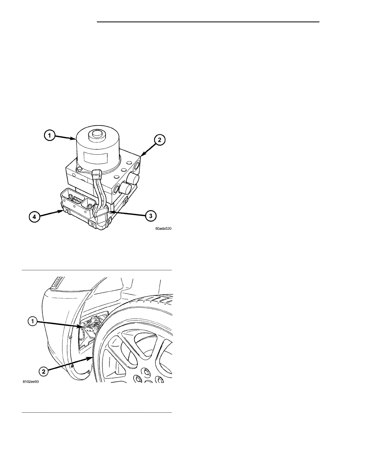
Fig. 6 Integrated Control Unit (Typical)
1 - PUMP/MOTOR
2 - HCU
3 - PUMP/MOTOR CONNECTOR
4 - CAB
Fig. 7 ICU Location
1 - ICU
2 - LEFT FRONT TIRE AND WHEEL ASSEMBLY
5 - 56 BRAKES - ABS ZB