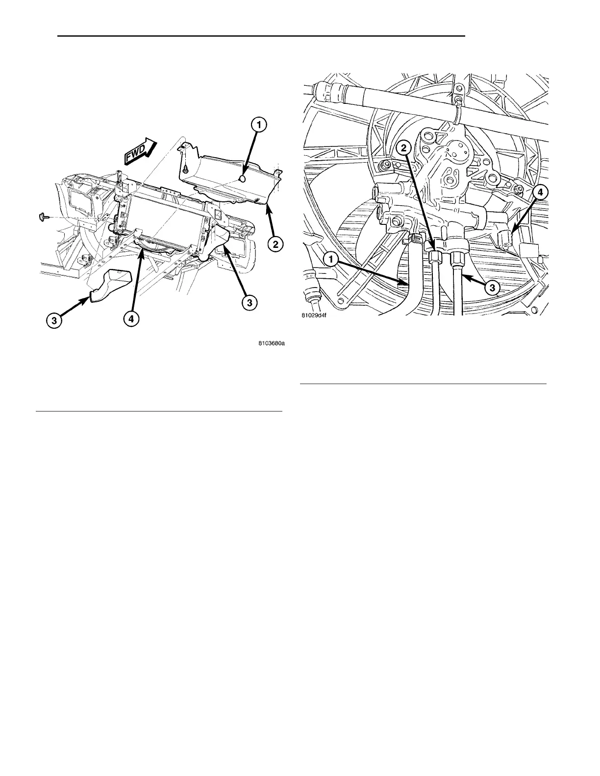
(3) Remove push pins from lower air dam that con-
nect to radiator fan shroud (Fig. 21).
(4) Lower vehicle.
(5) Disconnect the electrical connector for the fan
control solenoid (Fig. 22).
NOTE: The hydraulic fan drive is driven by the
power steering pump. When removing lines or
hoses from fan drive assembly use a drain pan to
catch any power steering fluid that may exit the fan
drive or the lines and hoses.
NOTE: When ever the high pressure line fittings are
removed from the hydraulic fan drive the O-rings
must be replaced.
(6) Disconnect two high pressure lines at hydraulic
fan drive (Fig. 22). Remove and discard o-rings from
line fittings.
(7) Disconnect low pressure return hose at hydrau-
lic fan drive (Fig. 22).
(8) Unclip hydraulic lines from radiator fan
shroud.
(9) Remove the radiator fan mounting fasteners
(Fig. 23).
(10) Remove the shroud and fan drive from vehi-
cle.
INSTALLATION
CAUTION: There is an external ground wire con-
nected to the hydraulic fan drive located at the elec-
trical connector on the fan assembly. This ground
MUST remain connected at all times. Failure to
ensure ground wire is connected when engine is
operating can cause severe damage to the PCM.
(1) Position fan drive and shroud in vehicle.
(2) Install radiator fan mounting fasteners (Fig.
23). Tighten fasteners to 5 N·m (45 in. lbs.).
NOTE: Whenever the high pressure line fittings are
removed from the hydraulic fan drive the o-rings
located on the fittings must be replaced.
(3) Lubricate the o-rings on the fittings with power
steering fluid then connect inlet and outlet high pres-
sure lines to fan drive (Fig. 22). Tighten pressure
inlet line to 47 N·m (35 ft. lbs.). Tighten pressure
outlet line to 29 N·m (21 ft. lbs.).
(4) Connect low pressure return hose to fan drive
(Fig. 22).
(5) Clip hydraulic lines to radiator fan shroud.
(6) Connect electrical connector for hydraulic fan
control solenoid.
(7) Raise vehicle on hoist.
Fig. 21 Air Dam
1 - PUSH PIN(S)
2 - AIR DAM
3 - BRAKE COOLING AIR DUCT
4 - RADIATOR FAN SHROUD
Fig. 22 Hydraulic and Electrical Connections
1 - LOW PRESSURE RETURN HOSE
2 - HIGH PRESSURE LINE (OUTLET)
3 - HIGH PRESSURE LINE (INLET)
4 - FAN CONTROL SOLENOID CONNECTOR
ZB ENGINE 7 - 23
RADIATOR FAN (Continued)















 To Next Page