(b) Connect antenna lead connector in the front
of the instrument panel. Disconnect connector at
antenna module. There should be a great drop in
reception quality. If not OK, replace antenna mod-
ule.
REMOVAL
The antenna is integral to the windshield. For ser-
vice procedures, (Refer to 23 - BODY/STATIONARY
GLASS/WINDSHIELD - REMOVAL).
ANTENNA MODULE
DESCRIPTION
The antenna module is an electromagnetic circuit
component designed to capture and enhance RF
(Radio Frequency) signals in both the AM and FM
broadcast bands. The antenna module is mounted
under the right front corner of the instrument panel.
The module is grounded through the mounting
bracket and fastener. The module has a one wire
electrical connector that connects to the integral
radio antenna, located in the windshield. There is an
electrical connector for battery voltage and a coax
cable connector.
OPERATION
The antenna module receives both AM and FM
radio signals supplied by the windshield integral
radio antenna system and selectively amplifies them.
The amplified signal is then sent through the coax
cable to the radio input.
DIAGNOSIS AND TESTING - ANTENNA
MODULE
Any diagnosis of the Audio system should
begin with the use of a scan tool and the appro-
priate Diagnostic Service Manual.
Refer to the appropriate wiring information.
WARNING: DISABLE THE AIRBAG SYSTEM
BEFORE ATTEMPTING ANY STEERING WHEEL,
STEERING COLUMN, SEAT BELT TENSIONER, SIDE
AIRBAG, OR INSTRUMENT PANEL COMPONENT
DIAGNOSIS OR SERVICE. DISCONNECT AND ISO-
LATE THE BATTERY NEGATIVE (GROUND) CABLE,
THEN WAIT TWO MINUTES FOR THE AIRBAG SYS-
TEM CAPACITOR TO DISCHARGE BEFORE PER-
FORMING FURTHER DIAGNOSIS OR SERVICE. THIS
IS THE ONLY SURE WAY TO DISABLE THE AIRBAG
SYSTEM. FAILURE TO TAKE THE PROPER PRE-
CAUTIONS COULD RESULT IN ACCIDENTAL AIR-
BAG DEPLOYMENT AND POSSIBLE PERSONAL
INJURY.
For diagnostic procedures, (Refer to 8 - ELECTRI-
CAL/AUDIO/ANTENNA - DIAGNOSIS AND TEST-
ING)
REMOVAL
(1) Disconnect and isolate the battery negative
cable.
(2) Remove the Instrument panel (Refer to 23 -
BODY/INSTRUMENT PANEL/INSTRUMENT
PANEL ASSEMBLY - REMOVAL).
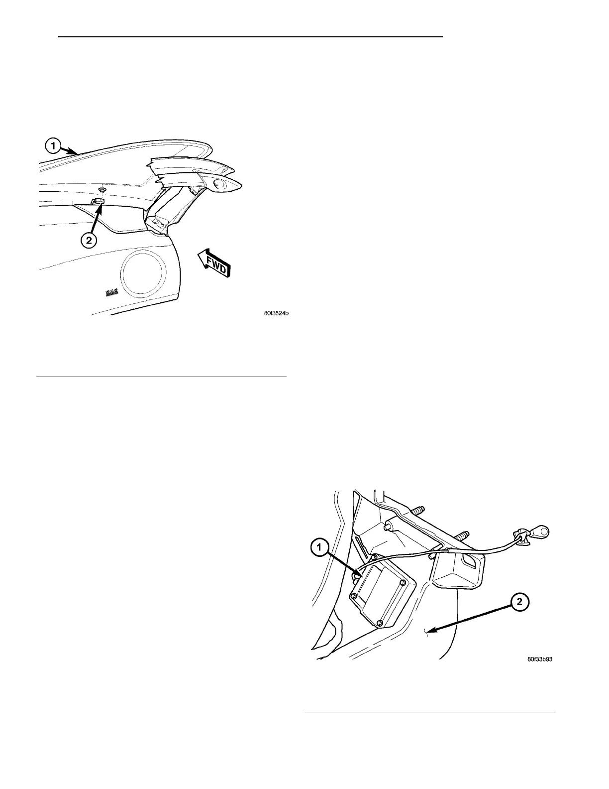
(3) Remove mounting fasteners from module (Fig.
3).
Fig. 2 ANTENNA MODULE CONNECTION TO
WINDSHIELD
1 - WINDSHIELD
2 - ANTENNA MODULE CONNECTOR
Fig. 3 ANTENNA MODULE
1 - ANTENNA MODULE
2 - INSTRUMENT PANEL
ZB AUDIO/VIDEO 8A - 5
ANTENNA (Continued)















 To Next Page