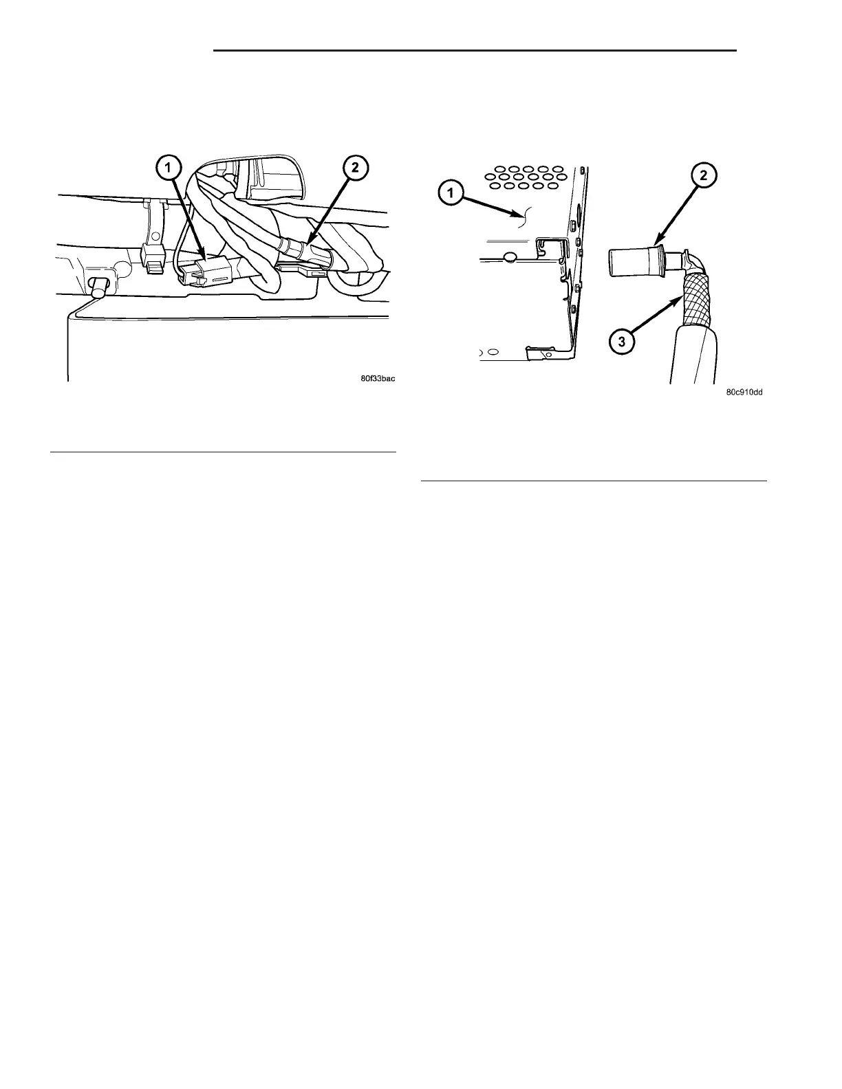
(4) Disconnect antenna module cable and electrical
harness connector (Fig. 4).
(5) Remove antenna module from instrument
panel.
INSTALLATION
(1) Install antenna module cable to instrument
panel harness and secure.
(2) Connect antenna module cable to instrument
panel antenna cable.
(3) Connect antenna module electrical harness con-
nector.
(4) Place antenna module into position and install
mounting fasteners.
(5) Install instrument panel (Refer to 23 - BODY/
INSTRUMENT PANEL/INSTRUMENT PANEL
ASSEMBLY - INSTALLATION).
(6) Connect battery negative cable.
INSTRUMENT PANEL
ANTENNA CABLE
REMOVAL
(1) Disconnect and isolate the battery negative
cable.
(2) Remove the instrument panel (Refer to 23 -
BODY/INSTRUMENT PANEL/INSTRUMENT
PANEL ASSEMBLY - REMOVAL).
(3) Disconnect the instrument panel cable from the
antenna module cable.
CAUTION: Pulling the antenna cable straight out of
the radio without pulling on the locking antenna
connector could damage the cable or radio.
(4) Disconnect the antenna cable by pulling the
locking antenna connector away from the radio (Fig.
5).
(5) Remove the antenna cable from the instrument
panel.
INSTALLATION
(1) Install antenna module cable to instrument
panel harness and secure.
(2) Connect instrument panel cable to antenna
module cable and to back of radio.
(3) Install instrument panel (Refer to 23 - BODY/
INSTRUMENT PANEL/INSTRUMENT PANEL
ASSEMBLY - INSTALLATION).
(4) Connect battery negative cable.
RADIO
DESCRIPTION
Available factory-installed radio receiver for this
model include:
• AM/FM/CD with 6 CD changer (RBQ sales code)
All factory-installed radio receivers can communi-
cate on the Programmable Communications Interface
(PCI) data bus network. All factory-installed receiv-
ers are stereo Electronically Tuned Radios (ETR) and
include an electronic digital clock function.
These radio receivers can only be serviced by an
authorized radio repair station. See the latest War-
ranty Policies and Procedures manual for a current
listing of authorized radio repair stations.
Fig. 4 ANTENNA MODULE CABLE
1 - ANTENNA MODULE ELECTRICAL CONNECTOR
2 - COAX CABLE
Fig. 5 ANTENNA TO RADIO
1 - RADIO
2 - LOCKING ANTENNA CONNECTOR
3 - INSTRUMENT PANEL ANTENNA CABLE
8A - 6 AUDIO/VIDEO ZB
ANTENNA MODULE (Continued)















 To Next Page